Lexus SC300 / Lexus SC400. Manual - part 464
 

  Index      Lexus     Lexus SC300 / Lexus SC400 - service repair manual


Search            


Content   ..  462  463  464  465   ..


Lexus SC300 / Lexus SC400. Manual - part 464


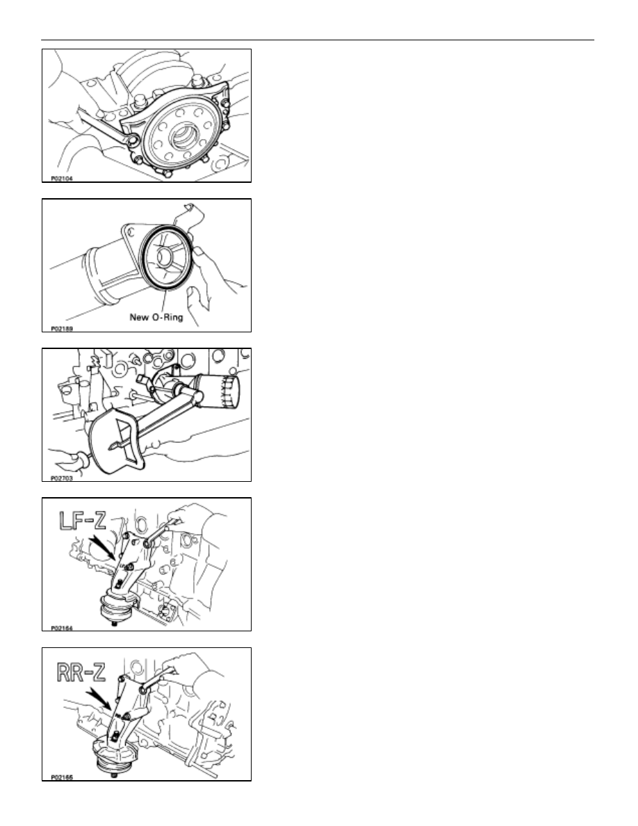
(c)  Install the retainer with the six bolts.

Torque: 5.9 

N

⋅

m (60 kgf

⋅

cm, 52 in.

⋅

lbf)

POST ASSEMBLY

(See Components on page EM–75)
1. 

INSTALL OIL PUMP (See page LU–15)

2. 

INSTALL OIL FILTER BRACKET
(a)  Place a new O–ring in position on the oil filter bracket.

(b)  Install a new gasket to the union bolt.
(c)  Install the oil filter bracket with the union bolt.

Torque:

88 N

⋅

m (900 kgf

⋅

cm, 65 ft

⋅

lbf)

3. 

INSTALL LH ENGINE MOUNTING BRACKET
Install the mounting bracket with the four bolts.

Torque:

58 N

⋅

m (590 kgf

⋅

cm, 43 ft

⋅

lbf)

HINT: The LH mounting bracket is marked ”LF–Z”.

4. 

INSTALL RH ENGINE MOUNTING BRACKET
Install the mounting bracket with the four bolts.

Torque:

58 N

⋅

m (590 kgf

⋅

cm, 43 ft

⋅

lbf)

HINT: The RH mounting bracket is marked ”RR–Z”.

EM–100

–

ENGINE MECHANICAL

Cylinder Block

5. INSTALL 

KNOCK 

SENSORS 

AND 

OIL 

PRESSURE

SWITCH
Using SST, install the two knock sensors and oil pressure
switch.
SST 09816–30010

Torque:

Knock sensor 

44 N

⋅

m

(450 kgf

⋅

cm, 33 ft

⋅

lbf)

Oil pressure switch  14 N

⋅

m

(150 kgf

⋅

cm, 11 ft

⋅

lbf)

6. 

INSTALL FUEL PIPE SUPPORT

Torque: 14 

N

⋅

m (145 kgf

⋅

cm, 10 ft

⋅

lbf)

7. 

INSTALL CYLINDER HEAD
(See pages EM–54 to 57)

Torque:

1st 34 N

⋅

m (350 kgf

⋅

cm, 25 ft

⋅

lbf)

2nd turn 90

°

3rd turn 90

°

8. 

INSTALL FUEL PRESSURE PULSATION DAMPER
(See step 1 on page FI–36)

Torque:

41 N

⋅

m (420 kgf

⋅

cm, 30 ft

⋅

lbf)

35 N

⋅

m (350 kgf

⋅

cm, 25 ft

⋅

lbf) for SST

9. 

INSTALL WATER PUMP AND BY–PASS PIPE

(a)  Install the water pump. (See page CO–7)
(b)  Install the No. 2 water by–pass pipe with the bolt.
(c)  Connect the No. 2 water by–pass hose to the engine hanger.
10. INSTALL  THROTTLE  BODY  WITH  INTAKE  AIR

CONNECTOR
(See page EM–18)

Torque:

21 N

⋅

m (210 kgf

⋅

cm, 15 ft

⋅

lbf)

11.  INSTALL TIMING PULLEYS AND BELT

(See pages EM–29 to 33)

12. INSTALL 

GENERATOR

Torque:

37 N

⋅

m (380 kgf

⋅

cm, 27 ft

⋅

lbf)

13.  REMOVE ENGINE STAND FROM ENGINE

–

ENGINE MECHANICAL

Cylinder Block

EM–101

14. (M/T)

INSTALL FLYWHEEL
HINT: The flywheel bolts are tightened in two progressive
steps, (b) and (d).
(a)  Install the flywheel on the crankshaft.
(b)  Install and uniformly tighten the eight mount bolts in

several passes in the sequence shown.

Torque:

49 N

⋅

m (500 kgf

⋅

cm, 36 ft

⋅

lbf)

(c)  Mark the flywheel bolt with paint.

(d)  Second, retighten the flywheel bolts by an additional

90


.

(e)  Check that the painted mark is now at a 90


 angle to (c).

15. (A/T)

INSTALL DRIVE PLATE
(a)  Apply adhesive to two or three threads of the mounting

bolt end.

Adhesive: Part No. 08833–00070, THREE BOND 1324 or
equivalent

(b)  Install the front spacer, drive plate and rear spacer on

the crankshaft.

(c)  Install and uniformly tighten the eight mounting bolts in

several passes in the sequence shown.

Torque:

98 N

⋅

m (1,000 kgf

⋅

cm, 72 ft

⋅

lbf)

EM–102

–

ENGINE MECHANICAL

Cylinder Block

ASSEMBLY OF ENGINE AND
TRANSMISSION

(See Components on page EM–73)

1. (M/T)

INSTALL CLUTCH DISC AND COVER

Torque:

19 N

⋅

m (195 kgf

⋅

cm, 14 ft

⋅

lbf)

2. 

ASSEMBLE ENGINE AND TRANSMISSION
(See page AT–31)

Torque:

14 mm head bolt 37 N

⋅

m (380 kgf

⋅

cm, 27 ft

⋅

lbf)

17 mm head bolt 72 N

⋅

m (730 kgf

⋅

cm, 53 ft

⋅

lbf)

3. INSTALL 

STARTER

Torque:

39 N

⋅

m (400 kgf

⋅

cm, 29 ft

⋅

lbf)

4. 

CONNECT ENGINE WIRE TO TRANSMISSION

5. (A/T)

INSTALL OIL COOLER PIPE

Torque:

34 N

⋅

m (350 kgf

⋅

cm, 25 ft

⋅

lbf)

6. (A/T)

INSTALL OIL DIPSTICK GUIDE FOR TRANSMISSION

–

ENGINE MECHANICAL

Cylinder Block

EM–103


Content   ..  462  463  464  465   ..