Lexus SC300 / Lexus SC400. Manual - part 437
 

  Index      Lexus     Lexus SC300 / Lexus SC400 - service repair manual


Search            


Content   ..  435  436  437  438   ..


Lexus SC300 / Lexus SC400. Manual - part 437


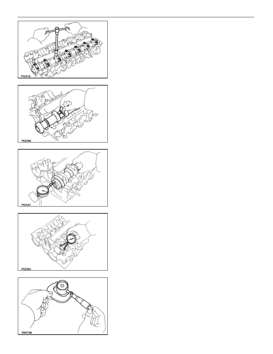
(e)  Remove the bearing caps.

(f)  Measure the Plastigage at its widest point.

Standard oil clearance:

 0.035–0.072 mm

(0.0014–0.0028 in.)

Maximum oil clearance: 

0.10 mm (0.039 in.)

If the oil clearance is greater than maximum, replace the cam-
shaft. If necessary, replace the bearing caps and cylinder
head as a set.
(g)  Completely remove the Plastigage.

F. 

Inspect camshaft thrust clearance
(a)  Install the camshafts.
(See step 2 on page EM–55)
(b)  Using a dial indicator, measure the thrust clearance

while moving the camshaft back and forth.

Standard thrust clearance:  0.080–0.190 mm

(0.0031–0.0075 in.)

Maximum thrust clearance:  0.30 mm (0.0118 in.)

If the thrust clearance is greater than maximum, replace the
camshaft. If necessary, replace the bearing caps and cylin-
der head as a set.

11.  INSPECT VALVE LIFTERS AND LIFTER BORES

(a)  Using a caliper gauge, measure the lifter bore diameter

of the cylinder head.

Lifter bore diameter: 

31.000–31.016 mm

(1.2205–1.2211 in.)

(b)  Using a micrometer, measure the lifter diameter.

Lifter diameter: 

30.966–30.976 mm

(1.2191–1.2195 in.)

EM–50

–

ENGINE MECHANICAL

Cylinder Head

(c)  Subtract the lifter diameter measurement from the lifter

bore diameter measurement.

Standard oil clearance: 

0.024–0.050 mm

(0.0009–0.0020 in.)

Maximum oil clearance: 

0.07 mm (0.0028 in.)

If the oil clearance is greater than maximum, replace the lifter.
If necessary, replace the cylinder head.

12.  INSPECT AIR INTAKE CHAMBER

Using a precision straight edge and feeler gauge, measure
the surfaces contacting the intake manifold for warpage.

Maximum warpage: 

0.15 mm (0.0059 in.)

If warpage is greater than maximum, replace the chamber.

13. INSPECT 

INTAKE 

MANIFOLD

Using a precision straight edge and feeler gauge, measure
the surfaces contacting the cylinder head and air intake
chamber for warpage.

Maximum warpage: 

0.15 mm (0.0059 in.)

If warpage is greater than maximum, replace the manifold.

14.  INSPECT EXHAUST MANIFOLDS

Using a precision straight edge and feeler gauge, measure
the surfaces contacting the cylinder head for warpage.

Maximum warpage: 

0.8 mm (0.031 in.)

If warpage is greater than maximum, replace the manifold.

15.  INSPECT CYLINDER HEAD BOLTS

Using a vernier caliper, measure the thread outside diameter
of the bolt.

Standard outside diameter: 10.8–11.0 mm

(0.425–0.433 in.)

Minimum outside diameter: 10.7 mm (0.421 in.)

If the diameter is less than minimum, replace the bolt.

–

ENGINE MECHANICAL

Cylinder Head

EM–51

ASSEMBLY OF CYLINDER HEAD

(See Components on page EM–35)

HINT:

•

Thoroughly clean all parts to be assembled.

•

Before installing the parts, apply new engine oil to all
sliding and rotating surfaces.

•

Replace all gaskets and oil seals with new ones.

1. INSTALL 

HEATER 

UNION

HINT: When using a new cylinder head, heater union must be
installed.
(a)  Apply adhesive to the end of the heater union as shown

in the illustration.

Adhesive: Part No. 08833–00070, THREE BOND 1324 or

equivalent

(b)  Using a wooden block and hammer, tap in a new heater

union, leaving 73 mm (2.87 in.) protruding from the
cylinder head.

NOTICE: Do not tap it in too far.

2. 

INSTALL EGR COOLER
Install a new gasket and EGR cooler with the eight bolts.

Torque: 14 

N

⋅

m (140 kgf

⋅

cm, 10 ft

⋅

lbf)

3.  INSTALL ENGINE COOLANT TEMPERATURE SENSOR

AND SENDER GAUGE

Torque: 20 

N

⋅

m (200 kgf

⋅

cm, 14 ft

⋅

lbf)

4.  INSTALL GROUND STRAP AND THROTTLE CABLE

BRACKET

5. 

INSTALL ENGINE HANGERS

Torque: 39 

N

⋅

m (400 kgf

⋅

cm, 29 ft

⋅

lbf)

EM–52

–

ENGINE MECHANICAL

Cylinder Head

3. INSTALL 

VALVES

(a)  Install new oil seal on the valve guide bushing.

HINT: The intake valve oil seal is brown and the exhaust valve
oil seal is black.

(b)  Install the following parts:

(1) Valve
(2) Spring seat
(3) Valve spring
(4) Spring retainer

HINT: Install the valve spring, facing the painted mark up-
ward.

(c) Using 

SST, 

compress the valve spring and place the two

keepers around the valve stem.

SST 09202–70010

–

ENGINE MECHANICAL

Cylinder Head

EM–53


Content   ..  435  436  437  438   ..