Lexus SC300 / Lexus SC400. Manual - part 415
 

  Index      Lexus     Lexus SC300 / Lexus SC400 - service repair manual


Search            


Content   ..  413  414  415  416   ..


Lexus SC300 / Lexus SC400. Manual - part 415


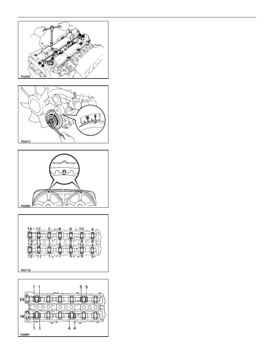
9.  REMOVE NO. 3, NO. 1 AND NO. 2 CYLINDER HEAD

COVERS
(a)  Remove the 12 bolts and four nuts.
(b)  Remove the cylinder head covers and gaskets.

10.  SET NO. 1 CYLINDER TO TDC/COMPRESSION

(a)  Turn the crankshaft pulley and align its groove with

timing mark ”0” of the No. 1 timing belt cover.

NOTICE: Always turn the crankshaft clockwise.

(b)  Check that the timing marks of the camshaft timing

pulleys are aligned with the timing marks of the No. 4
timing belt cover.

If not, turn the crankshaft one revolution (360

°

).

11. INSPECT 

VALVE 

CLEARANCE

(a)  Uniformly tighten the bearing cap bolts in several

passes.

Torque: 20 N

⋅

m (200 kgf

⋅

cm, 14 ft

⋅

lbf)

(b)  Check only those valves indicated in the illustration.

•

Using a feeler gauge, measure the clearance
between the valve lifter and camshaft.

•

Record the valve clearance measurements of
those that are out of specification. They will be used
later to determine the required replacement
adjusting shim.

Valve clearance (Cold):

Intake 0.15–0.25 mm (0.006–0.010 in.)

Exhaust 0.25–0.35 mm (0.010–0.014 in.)

EM–12

–

ENGINE MECHANICAL

Engine Tune–Up

(c)  Turn the crankshaft 2/3 of a revolution (240


), check

only the valves indicated in the illustration.

Measure the valve clearance.
[See procedure in step (b)]

(d)  Turn the crankshaft a further 2/3 of a revolution (240


),

check only the valves indicated in the illustration.

Measure the valve clearance.
[See procedure in step (b)]

12. ADJUST 

VALVE 

CLEARANCE

(a)  Remove the adjusting shim.

•

Turn the camshaft so that the cam lobe for the valve
to be adjusted faces up.

•

Turn the valve lifter with a screwdriver so that the
notches would be per pendicular to the camshaft.

•

Using SST (A), press down the valve lifter and
place SST (B) between the camshaft and valve
lifter. Remove SST (A).

SST 09248–55020

(09248–05011 (A), 09248–05021 (B))

HINT:

•

Choose either method A or B in using SST on either side
of the cam lobe.

–

ENGINE MECHANICAL

Engine Tune–Up

EM–13

•

Position SST on the edge of the lifter for easy removal
of the shim.

•

Remove the adjusting shim with a small screwdriver and
a magnetic finger.

(b) Determine the replacement adjusting shim size

according to the following formula or Charts:

•

Using a micrometer, measure the thickness of the
removed shim.

•

Calculate the thickness of a new shim so the valve
clearance comes within specified value.
T

 Thickness of used shim

A

 Measured valve clearance

N

 Thickness of new shim

Intake N = T + (A–0.20 mm)
Exhaust N = T + (A–0.30 mm)

•

Select a new shim with a thickness as close as
possible to the calculated values.

HINT: Shims are available in seventeen sizes in increments
of 0.05 mm, from 2.50 mm to 3.30 mm.
(c)  Install a new adjusting shim.

•

Place a new adjusting shim on the valve lifter, with
imprinted numbers facing down.

•

Press down the valve lifter with SST (A), and
remove SST (B).

SST 09248–55020
(d)  Recheck the valve clearance.

EM–14

–

ENGINE MECHANICAL

Engine Tune–Up

–

ENGINE MECHANICAL

Engine Tune–Up

EM–15


Content   ..  413  414  415  416   ..