Lexus SC300 / Lexus SC400. Manual - part 277
 

  Index      Lexus     Lexus SC300 / Lexus SC400 - service repair manual


Search            


Content   ..  275  276  277  278   ..


Lexus SC300 / Lexus SC400. Manual - part 277


NG

OK

OK

NG

INSPECTION PROCEDURE

1

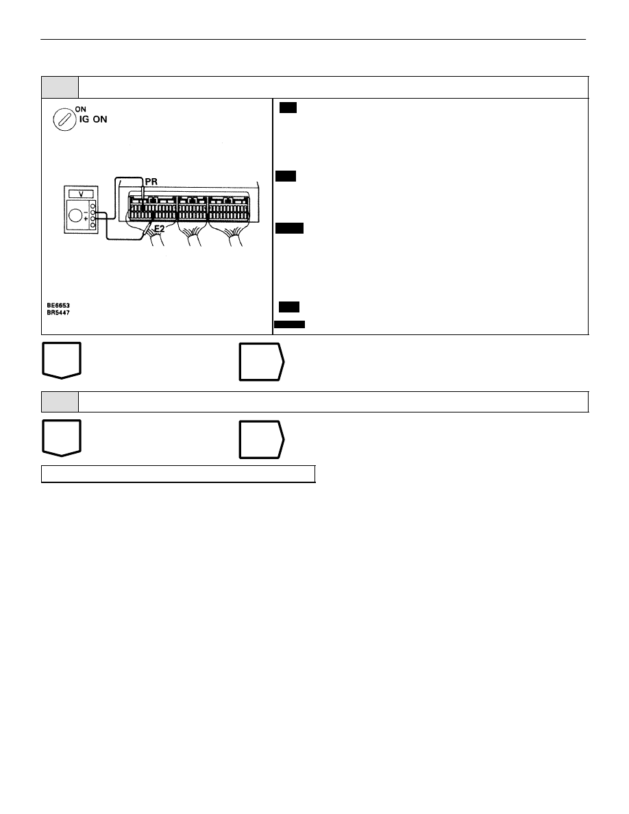
Check voltage between terminals PR and E2 of ABS & TRAC ECU connector.

C

OK

P

C

Notice

1.

Remove ABS & TRAC ECU with connectors still
connected.

2.

Operate the engine for about 30 seconds at idle
speed to raise the pressure of TRAC actuator to a
high level.

1.

Stop the engine and then turn ignition switch ON.

2.

Measure voltage between terminals PR and E2 of
ABS & TRAC ECU connector.

Voltage:

4 – 8 V

1.

Drain the fluid out of the actuator to reduce the pres-
sure (See page 

BR–48

).

2.

Measure voltage between terminals PR and E2 of
ABS & TRAC ECU connector.

Voltage:

10 – 14 V

Add fluid to reservoir after the check.

Check and replace ABS & TRAC ECU.

2

Check harness and connector between ABS & TRAC ECU and TRAC actuator (See page 

IN–33

).

Repair or replace harness or connector.

Replace TRAC actuator.

BR–136

–

BRAKE SYSTEM

ANTI–LOCK BRAKE SYSTEM (ABS)

–MEMO–

–

BRAKE SYSTEM

ANTI–LOCK BRAKE SYSTEM (ABS)

BR–137

WIRING DIAGRAM

DTC

61

TRAC ECU Communication Circuit Malfunc-
tion.

CIRCUIT DESCRIPTION

DTC No.

DTC Detecting Condition

Trouble Area

61

Either of the following (1) or (2) continues for


more than

8 sec.:

(1) Vehicle speed signal of 4 wheels is less than 1 km/h

(1 mph) when TRCO signal is input.

(2) THFA signal is 0V when TRCO signal is not input.

Open or short in THFA, TRCO circuit

ABS & TRAC ECU

TRAC ECU

DIAGNOSTIC CHART

DIAGNOSTIC CHART

BR–138

–

BRAKE SYSTEM

ANTI–LOCK BRAKE SYSTEM (ABS)

OK

OK

OK

NG

OK

NG

INSPECTION PROCEDURE

1

Check voltage between terminals THFA, TRCO of ABS & TRAC ECU and body ground.

C

OK

P

Remove ABS & TRAC ECU with connectors still con-
nected.

Measure voltage between terminals THFA, TRCO of
ABS & TRAC ECU and body ground when ignition
switch is turned ON.

Voltage:

10 – 14 V

Check and replace ABS & TRAC ECU.

2

Check for open and short in harness and connector between ABS & TRAC ECU and TRAC ECU
(See page 

IN–33

).

Repair or replace harness or connector.

3

Check voltage of terminals THFA, TRCO of TRAC ECU.

C

OK

P

Disconnect ABS & TRAC ECU connector.

Measure voltage between terminals THFA, TRCO of
TRAC ECU and body ground when ignition switch is
turned ON.

Voltage:

10 – 14 V

Check and replace TRAC ECU.

Check and replace ABS & TRAC ECU.

–

BRAKE SYSTEM

ANTI–LOCK BRAKE SYSTEM (ABS)

BR–139


Content   ..  275  276  277  278   ..