Lexus SC300 / Lexus SC400. Manual - part 163
Parts Inspection
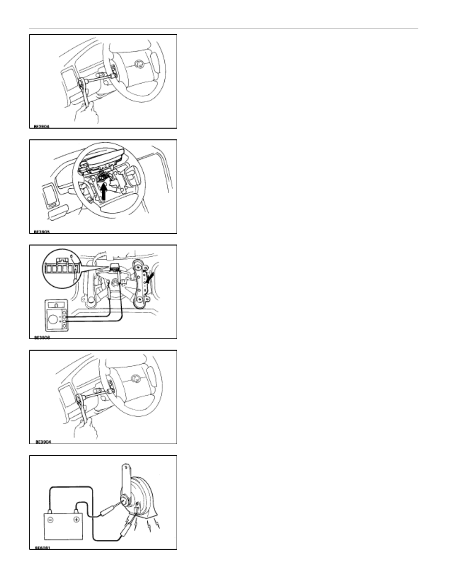
(Horn Switch)
INSPECTION OF HORN SWITCH
INSPECT HORN SWITCH
(a) Disconnect the negative (–) terminal from the battery.
(b) Remove the left and right covers from the steering wheel.
(c) Using a torx wrench, loosen the four bolts.
(d) Pull up the horn pad and place it on the steering column as
shown.
HINT: Do not disconnect the connector from the horn pad.
(e) Disconnect the connector from the slip ring.
(f) Check that there is no continuity between terminal 6 of the
connector and body ground.
(g) Check that there is continuity between terminal 6 of the
connector and body ground when the horn contact plate is
pressed against the steering spoke assembly.
If continuity is not as specified, repair or replace the steering
wheel or wire harness as necessary.
(h) Install the horn pad in place and using a torx wrench, tighten
the four bolts.
Torque: 7.1 N
⋅
m (72 kgf
⋅
cm, 62 in.
⋅
lbf)
(i)
Install the left and right covers.
(j)
Connect the negative (–) terminal to the battery.
(Horn)
INSPECTION OF HORN
INSPECT HORN OPERATION
Connect the positive (+) lead from the battery to the terminal
and negative (–) lead to the horn body and check that the
horn blows.
If operation is not as specified, replace the horn.
–
BODY ELECTRICAL SYSTEM
HORN SYSTEM
BE–263