Lexus LS400 (2000 year). Manual - part 67
 

  Index      Lexus     Lexus LS400 (RM717U) - service repair manual 2000 year


Search            


Content   ..  65  66  67  68   ..


Lexus LS400 (2000 year). Manual - part 67


BE0C2–01

I03455

I03456

I03457

N12966

N12967

BE–96

–

BODY ELECTRICAL

COMBINATION METER

1959

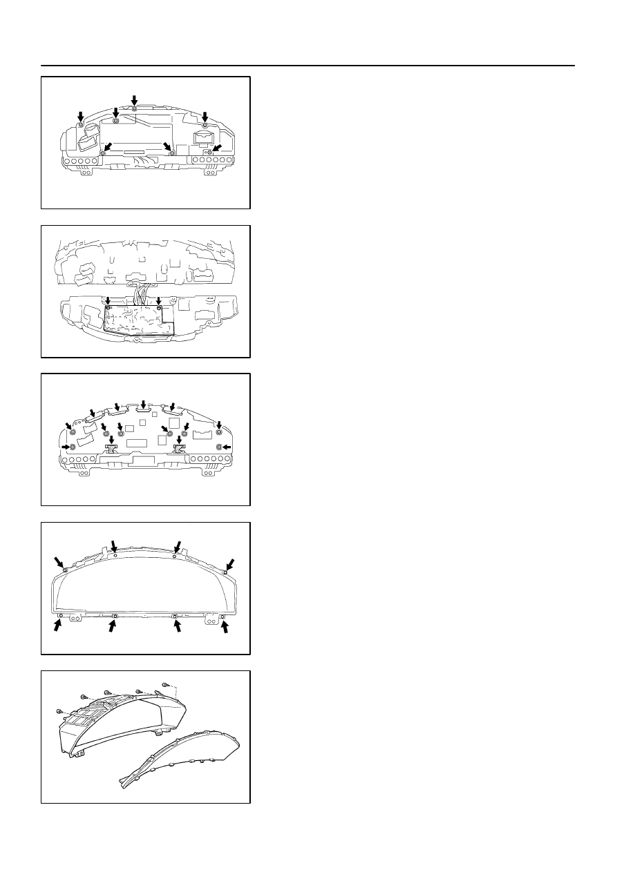
DISASSEMBLY

1.

REMOVE COVER

(a)

Remove the 7 screws.

(b)

Disconnect the cover from the meter case.

2.

REMOVE COMBINATION METER ECU (No.2)

(a)

Remove the 2 screws.

(b)

Disconnect the connector.

3.

REMOVE COMBINATION METER ECU (No.1)

(a)

Remove the 8 screws and 6 connectors.

(b)

Remove the power source unit from the meter case.

4.

REMOVE METER HOOD

Remove the 8 screws and the meter hood from the meter case.

5.

REMOVE METER GLASS

Remove the 5 screws and the meter glass.
6.

REMOVE METER LENS FROM CASE

Separate the meter lens together with the speedometer,
tachometer and 2 gauges from the meter.

I03458

I03459

BE4630

Lens

Meter
(Speed, Tacho)

I03460

I03490

–

BODY ELECTRICAL

COMBINATION METER

BE–97

1960

7.

REMOVE FUEL AND TEMPERATURE GAUGE

Release and separate the 2 gauges from the lens.

8.

REMOVE SPEEDOMETER AND TACHOMETER

(a)

Remove the 4 screws, and the speedometer and tachom-
eter.

(b)

Keep the indicator needle horizontal.

(c)

Remove the indicator needle taking care not to strike the
lens.

9.

REMOVE 2 COLD CATHODE TUBES

(a)

Remove the 4 screws and 2 clips.

(b)

Remove the 2 cold cathode tubes.

(c)

Remove the 2 grommets.

(d)

Remove the A/T lens A and B.

10.

REMOVE CIRCUIT PLATE

(a)

Disconnect the A/T plate with the 2 screws.

(b)

Remove the 28 warning lights.

(c)

Remove the circuit plate from the case.

I03435

Wire Harness Side

”A”

”B”

”C”

BE0C3–02

BE–98

–

BODY ELECTRICAL

COMBINATION METER

1961

INSPECTION

1.

INSPECT COMBINATION METER CIRCUIT
Connector disconnected:

Disconnect connector ”A”, ”B” and ”C” from the combination
meter and inspect the connectors on the wire harness side as
follows.

Tester connection

Condition

Specified condition

A1 – A12

Driving monitor switch MODE Free

No continuity

A1 – A12

Driving monitor switch MODE Pushed in

Continuity

A2 – A12

Driving monitor switch RESET Free

No continuity

A2 – A12

Driving monitor switch RESET Pushed in

Continuity

A5 – A6

Light control switch TAIL or HEAD and

turn rheostat volume knob

Voltage changes no voltage or

voltage fluctuates

A8 – Ground

Ignition switch OFF or ACC

No voltage

A8 – Ground

Ignition switch ON or START

Battery positive voltage

B1 – Ground

Ignition switch OFF or ACC

No voltage

B1 – Ground

Ignition switch ON or START

Battery positive voltage

B3 – Ground

Engine running

Voltage fluctuates

B4 – Ground

Steering pad switch FUNCTION

Continuity

B4 – Ground

Steering pad switch RESET

Resistance 360 

Ω

B4 – Ground

Steering pad switch MODE

Resistance 1,110 

Ω

B5 – B12

Fuel Sender Gauge

Float position Full

Resistance Approx. 21 

Ω

B5 – B12

Fuel Sender Gauge

Float position 1/2

Resistance Approx. 145.8 

Ω

B5 – B12

Fuel Sender Gauge

Float position Empty

Resistance Approx. 276 

Ω

B5 – B13

Constant

Resistance Approx. 300 

Ω

B6 – Ground

Constant

Continuity

B7 – Ground

Constant

Battery positive voltage

B8 – Ground

Constant

Battery positive voltage

B16 – Ground

Constant

Continuity

C2 – Ground

Turn signal switch LEFT

Continuity

C3 – Ground

Constant

Continuity

I03500

Wire Harness Side

Connector ”F”

Connector ”E”

Connector ”G”

–

BODY ELECTRICAL

COMBINATION METER

BE–99

1962

C4 – Ground

Light control switch HI or FLASH

Battery positive voltage

C5 – Ground

Turn signal switch RIGHT

Continuity

C11 – Ground

Engine running

Continuity

C14 – Ground

Window washer level warning switch

Float down

Continuity

C17 – Ground

Brake fluid level warning switch Float down

Continuity

C18 – Ground

Constant

Continuity

If circuit is not as specified, wiring diagram and inspect the cir-
cuit connected to other parts.

2.

INSPECT COMBINATION METER CIRCUIT PLATE
Warning light circuit plate:

(a)

Remove the cover.

(b)

Disconnect connector ”E”, ”F” and ”G” from the combina-
tion meter and inspect the connectors on the wire harness
side as follows.

Tester connection

Check indicator light circuit

specified condition

E1 (–) – F14 (+)

Headlight indicator (USA models)

Taillight indicator (CANADA models)

Continuity

E6 (–) – G16 (+)

E6 (–) – G17 (+)

TRAC indicator light

Continuity

E7 (–) – G16 (+)

E7 (–) – G17 (+)

Window washer level warning light

Continuity

E8 (–) – G16 (+)

E8 (–) – G17 (+)

Malfunction indicator light

Continuity

E9 (+) – E10 (–)

VSC OFF indicator light

Continuity

E11 (–) – G16 (+)

E11 (–) – G17 (+)

ABS warning light

Continuity

E12 (+) – E13 (–)

HEIGHT HI indicator light

Continuity

E14 (–) – G16 (+)

E14 (–) – G17 (+)

ECT SNOW indicator light

Continuity

E16 (–) – G16 (+)

E16 (–) – G17 (+)

ECT PWR indicator light

Continuity

F5 (–) – G16 (+)

F5 (–) – G17 (+)

A/T shift indicator light (2)

Continuity


Content   ..  65  66  67  68   ..