Lexus LS400 (2000 year). Manual - part 38
 

  Index      Lexus     Lexus LS400 (RM717U) - service repair manual 2000 year


Search            


Content   ..  36  37  38  39   ..


Lexus LS400 (2000 year). Manual - part 38


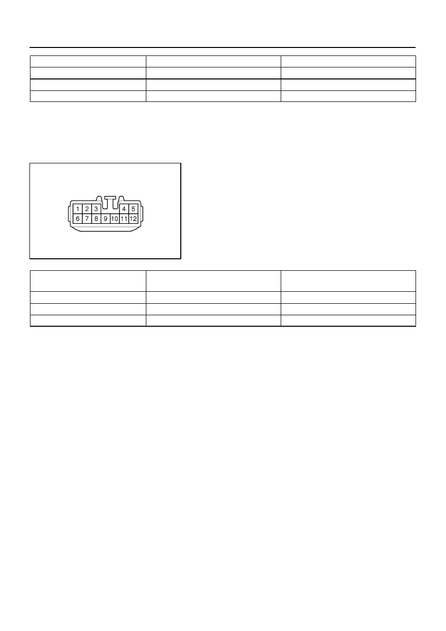
I03484

Wire Harness Side

–

BODY ELECTRICAL

AUDIO SYSTEM

BE–229

2092

Tester connection

Condition

Specified condition

B7 – Ground

Constant

Continuity

B4 – Ground

Constant

Battery positive voltage

C12 – Ground

Ignition switch position ACC or ON

Battery positive voltage

If circuit is not as specified, inspect the circuits connected to oth-
er parts.

6.

Pioneer made and LEXUS navigation system:
INSPECT CD AUTO CHANGER CIRCUIT

Disconnect the connectors from the controller and inspect the
connector on the wire harness side, as shown.

Tester connection to

terminal number

Condition

Specified condition

5 – Ground

Constant

Battery positive voltage

12 – Ground

Ignition switch LOCK

No voltage

12 – Ground

Ignition switch ACC or ON

Battery positive voltage

If circuit is not as specified, inspect the circuits connected to oth-
er parts.
HINT:
Since the signals to and from the AP+, AP–, SGND, GND1 ter-
minals are serial signals, they cannot ordinarily be measured
with a tester.

I03485

Wire Harness Side

Connector ”A”

Connector ”B”

Connector ”C”

BE–230

–

BODY ELECTRICAL

AUDIO SYSTEM

2093

7.

LEXUS navigation system:
INSPECT RADIO RECEIVER ASSEMBLY CIRCUIT

Disconnect the connectors from the radio receiver assembly.
And inspect the connector on the wire harness side, as shown.

Tester connection

Condition

Specified condition

B2 – Ground

Constant

Continuity

B1 – Ground

Ignition switch position ACC or ON

Battery positive voltage

B1 – Ground

Ignition switch position LOCK

No voltage

B4 – Ground

Constant

Battery positive voltage

If circuit is not as specified, inspect the circuits connected to oth-
er parts.
HINT:
Check the wire harness between power amplifier and the CD
auto changer, between radio receiver assembly and power am-
plifier.
8.

INSPECT GLASS PRINTED ANTENNA

(Use same procedure as for ”INSPECT DEFOGGER WIRES”
on page 

BE–116

)

9.

REPAIR GLASS PRINTED ANTENNA

(Use same procedure as for ”REPAIR DEFOGGER WIRES” on
page 

BE–116

)

BE0B8–01

Z14947

–

BODY ELECTRICAL

POWER SOURCE

BE–23

1886

INSPECTION

1.

INSPECT INSTRUMENT PANEL JUNCTION BLOCK

BE–24

–

BODY ELECTRICAL

POWER SOURCE

1887

2.

FUSE CIRCUIT

Remove the fuse from the junction block and inspect the con-
nector on junction block side.
Connect numbers are shown in the illustration.

Fuse

Tester connection

Condition

Specified condition

PANEL

3 – Ground

Light control switch TAIL or HEAD

Battery positive voltage

A/C

5 – Ground

Constant

Battery positive voltage

ECU–IG

10 – Ground

Ignition switch ON

Battery positive voltage

TURN

12 – Ground

Ignition switch ON

Battery positive voltage

WASHER

14 – Ground

Ignition switch ON

Battery positive voltage

ST

15 – Ground

Ignition switch START

Battery positive voltage

P RR DOOR

18 – Ground

Constant

Battery positive voltage

FUEL OPN

20 – Ground

Constant

Battery positive voltage

PWR–IG

21 – Ground

Ignition switch ON

Battery positive voltage

WIPER

24 – Ground

Ignition switch ON

Battery positive voltage

AIR SUS

25 – Ground

Ignition switch ON

Battery positive voltage

TAIL

27 – Ground

Light control switch TAIL or HEAD

Battery positive voltage

STOP

29 – Ground

Constant

Battery positive voltage

RR CIG

32 – Ground

Ignition switch ACC or ON

Battery positive voltage

GAUGE

33 – Ground

Ignition switch ON

Battery positive voltage

HEATER

35 – Ground

Ignition switch ON

Battery positive voltage

D RR DOOR

38 – Ground

Constant

Battery positive voltage

STOP–S

39 – Ground

Stop light switch ON

Battery positive voltage

RADIO No.2

42 – Ground

Ignition switch ACC or ON

Battery positive voltage

FR CIG

44 – Ground

Ignition switch ACC or ON

Battery positive voltage

IGN

46 – Ground

Ignition switch ON

Battery positive voltage

FR FOG

47 – Ground

Constant

Battery positive voltage

SEAT FR H

49 – Ground

Constant

Battery positive voltage

PWR H

51 – Ground

Constant

Battery positive voltage

If the circuit is not as specified, inspect the circuit connected to
other parts.


Content   ..  36  37  38  39   ..