Lexus GS300/400 (2000 year). Manual - part 138
 

  Index      Lexus     Lexus GS300/400 - service repair manual 2000 year


Search            


Content   ..  136  137  138  139   ..


Lexus GS300/400 (2000 year). Manual - part 138


Z02456

Width

75

°

45

°

A02710

Z02457

Deviation

EM0801

EM0281

EM–44

–

ENGINE MECHANICAL (2JZ–GE)

CYLINDER HEAD

1398

(2)

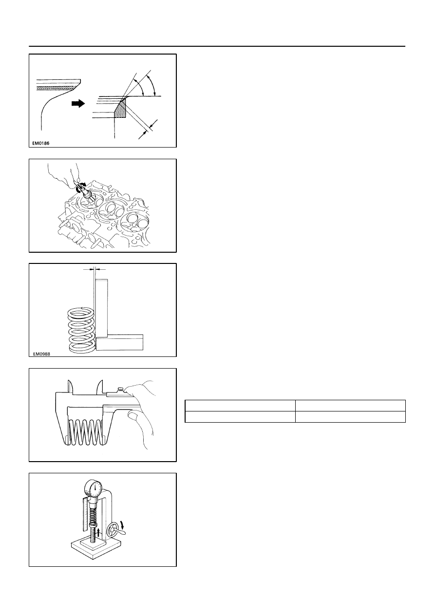
If the seating is too low on the valve face, use 75

°

and 45

°

 cutters to correct the seat.

(d)

Hand–lap the valve and valve seat with an abrasive com-
pound.

(e)

After hand–lapping, clean the valve and valve seat.

8.

INSPECT VALVE SPRINGS

(a)

Using a steel square, measure the deviation of the valve
spring.
Maximum deviation: 2.0 mm (0.079 in.)

If deviation is greater than maximum, replace the valve spring.

(b)

Using vernier calipers, measure the free length of the
valve spring.
Free length:

Pink painted mark

43.71 mm (1.7209 in.)

Yellow painted mark

44.10 mm (1.7362 in.)

If the free length is not as specified, replace the valve spring.

(c)

Using a spring tester, measure the tension of the valve
spring at the specified installed length.
Installed tension:
186.2 – 205.8 N (19.0 – 21.0 kgf, 41.9 – 46.3 lbf)
at 34.5 mm (1.358 in.)

If the installed tension is not as specified, replace the valve
spring.

A02820

EM2011

EM2538

A02817

Plastigage

–

ENGINE MECHANICAL (2JZ–GE)

CYLINDER HEAD

EM–45

1399

9.

INSPECT CAMSHAFTS FOR RUNOUT

(a)

Place the camshaft on V–blocks.

(b)

Using a dial indicator, measure the circle runout at the
center journal.
Maximum circle runout: 0.08 mm (0.0031 in.)

If the circle runout is greater than maximum, replace the cam-
shaft.

10.

INSPECT CAM LOBES
Using a micrometer, measure the cam lobe height.
Standard cam lobe height:

Intake

44.310 – 44.360 mm (1.7445 – 1.7465 in.)

Exhaust

44.250 – 44.350 mm (1.7421 – 1.7461 in.)

Minimum cam lobe height:

Intake

44.16 mm (1.7386 in.)

Exhaust

44.10 mm (1.7362 in.)

If the cam lobe height is less than minimum, replace the cam-
shaft.

11.

INSPECT CAMSHAFT JOURNALS
Using a micrometer, measure the journal diameter.
Journal diameter:
28.949 – 28.965 mm (1.1397 – 1.1404 in.)

If the journal diameter is not as specified, check the oil clear-
ance.
12.

INSPECT CAMSHAFT BEARING
Check the bearings for flaking and scoring.

If the bearings are damaged, replace the bearing caps and cyl-
inder head as a set.
13.

INSPECT CAMSHAFT JOURNAL OIL CLEARANCE

(a)

Clean the bearing caps and camshaft journals.

(b)

Place the camshafts on the cylinder head.

(c)

Lay a strip of Plastigage across each of the camshaft jour-
nals.

(d)

Install the bearing caps. (See page 

EM–52

)

Torque: 20 N·m (200 kgf·cm, 14 ft·lbf)

NOTICE:
Do not turn the camshaft.
(e)

Remove the bearing caps.

A02718

A02815

A02688

EM–46

–

ENGINE MECHANICAL (2JZ–GE)

CYLINDER HEAD

1400

(f)

Measure the Plastigage at its widest point.
Standard oil clearance:
0.035 – 0.072 mm (0.0014 – 0.0028 in.)
Maximum oil clearance:
0.10 mm (0.0039 in.)

If the oil clearance is greater than maximum, replace the cam-
shaft. If necessary, replace the bearing caps and cylinder head
as a set.
(g)

Completely remove the Plastigage.

14.

INSPECT CAMSHAFT THRUST CLEARANCE

(a)

Install the camshafts. (See page 

EM–52

)

(b)

Using a dial indicator, measure the thrust clearance while
moving the camshaft back and forth.
Standard thrust clearance: 
0.080 – 0.190 mm (0.0031 – 0.0075 in.)
Maximum thrust clearance:
0.30 mm (0.0118 in.)

If the thrust clearance is greater than maximum, replace the
camshaft. If necessary, replace the bearing caps and cylinder
head as a set.

15.

INSPECT VALVE LIFTERS AND LIFTER BORES

(a)

Using a caliper gauge, measure the lifter bore diameter
of the cylinder head.
Lifter bore diameter:
31.000 – 31.016 mm (1.2205 – 1.2211 in.)

(b)

Using a micrometer, measure the lifter diameter.
Lifter diameter:
30.966 – 30.976 mm (1.2191 – 1.2195 in.)

(c)

Subtract the lifter diameter measurement from the lifter
bore diameter measurement.
Standard oil clearance:
0.024 – 0.050 mm (0.0009 – 0.0020 in.)
Maximum oil clearance:
0.07 mm (0.0028 in.)

If the oil clearance is greater than maximum, replace the lifter.
If necessary, replace the cylinder head.

A02830

A02829

A02831

A02828

About
50 mm

Compressed
Thread

–

ENGINE MECHANICAL (2JZ–GE)

CYLINDER HEAD

EM–47

1401

16.

INSPECT AIR INTAKE CHAMBER

Using a precision straight edge and feeler gauge, measure the
surfaces contacting the intake manifold for warpage.

Maximum warpage: 0.15 mm (0.0059 in.)

If warpage is greater than maximum, replace the chamber.

17.

INSPECT INTAKE MANIFOLD

Using a precision straight edge and feeler gauge, measure the
surfaces contacting the cylinder head and air intake chamber
for warpage.

Maximum warpage: 0.15 mm (0.0059 in.)

If warpage is greater than maximum, replace the manifold.

18.

INSPECT EXHAUST MANIFOLD

Using a precision straight edge and feeler gauge, measure the
surfaces contacting the cylinder head for warpage.

Maximum warpage: 0.50 mm (0.0196 in.)

If warpage is greater than maximum, replace the manifold.

19.

INSPECT CYLINDER HEAD BOLTS

Using a vernier caliper, measure the thread outside diameter of
the bolt.

Standard outside diameter:
10.8 – 11.0 mm (0.425 – 0.433 in.)
Minimum outside diameter:
10.7 mm (0.421 in.)

If the diameter is less than minimum, replace the bolt.


Content   ..  136  137  138  139   ..