Lexus GS300/400 (2000 year). Manual - part 87
 

  Index      Lexus     Lexus GS300/400 - service repair manual 2000 year


Search            


Content   ..  85  86  87  88   ..


Lexus GS300/400 (2000 year). Manual - part 87


I04051

Wire Harness Side

I04061

Open

Close

1

2

BE–62

–

BODY ELECTRICAL

INTERIOR LIGHT SYSTEM

2363

6.

INSPECT VANITY LIGHT CIRCUIT

Disconnect the connector from the light and inspect the con-
nector on the wire harness side, as shown.

Tester connection

Condition

Specified condition

2 – Ground

Constant

Continuity

1 – Ground

Constant

Battery positive voltage

If circuit is not as specified, inspect power source or wire har-
ness.

7.

Front door:
INSPECT DOOR COURTESY SWITCH CONTINUITY

(a)

Connect the connector to the front door ECU.

(b)

Check that continuity exists between terminals 1 and 2
when door is opened.

(c)

Check that no continuity exists between terminals 1 and
2 when door is closed.

If continuity is not as specified, replace the switch.
8.

Front door:
INSPECT DOOR COURTESY SWITCH CIRCUIT
Driver side: (See page 

DI–868

)

Passenger side: (See page 

DI–900

)

I04066

Open

Close

1

2

I04052

e–2–2–J

2

1

I04053

Wire Harness Side

I04054

1

2

–

BODY ELECTRICAL

INTERIOR LIGHT SYSTEM

BE–63

2364

9.

Rear door:
INSPECT DOOR COURTESY SWITCH CONTINUITY

(a)

Connect the connector to the rear door ECU.

(b)

Check that continuity exists between terminals 1 and 2
when door is opened.

(c)

Check that no continuity exists between terminals 1 and
2 when door is closed.

If continuity is not as specified, replace the switch.
10.

Rear door:
INSPECT DOOR COURTESY SWITCH CIRCUIT
Rear LH side: (See page 

DI–930

)

Rear RH side: (See page 

DI–947

)

11.

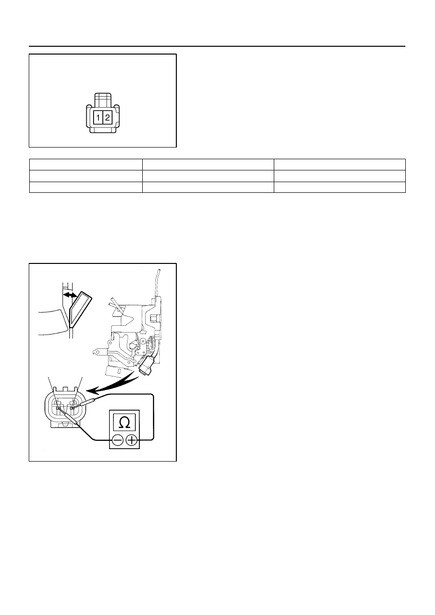
INSPECT DOOR COURTESY LIGHT CONTINUITY

Using an ohmmeter, check that continuity exists between termi-
nals.
If continuity is not as specified, replace the light assembly or
bulb.

12.

INSPECT DOOR COURTESY LIGHT CIRCUIT
Driver side: (See page 

DI–874

)

Passenger side: (See page 

DI–906

)

Rear LH side: (See page 

DI–934

)

Rear RH side: (See page 

DI–951

)

13.

INSPECT LUGGAGE COMPARTMENT DOOR COUR-
TESY SWITCH CONTINUITY

Switch position

Tester connection

Specified condition

OFF (closed)

–

No continuity

ON (opened)

2 – Switch body

Continuity

If continuity is not as specified, replace the switch.

I04185

Wire Harness Side

I04056

e–2–2–J

I04053

Wire Harness Side

BE–64

–

BODY ELECTRICAL

INTERIOR LIGHT SYSTEM

2365

14.

INSPECT LUGGAGE COMPARTMENT DOOR COUR-
TESY SWITCH CIRCUIT
(See page 

DI–792

)

Disconnect the connector from the switch and inspect the con-
nector on the wire harness side, as shown.

Tester connection

Condition

Specified condition

2 – Body ground

Luggage compartment door courtesy switch ON

(door opened)

Continuity

If circuit is not as specified, inspect power source or wire har-
ness.

15.

INSPECT LUGGAGE COMPARTMENT LIGHT CONTI-
NUITY

Using an ohmmeter, check that continuity exists between termi-
nals.
If continuity is not as specified, replace the light assembly or
bulb.

16.

INSPECT LUGGAGE COMPARTMENT LIGHT CIR-
CUIT

Disconnect the connector from the light and inspect the con-
nector on the wire harness side, as shown.

Tester connection

Condition

Specified condition

1 – Body ground

Constant

Continuity

If circuit is not as specified, inspect power source or wire har-
ness.

I04057

ON

OFF

1

2

I04058

Wire Harness Side

1

2

I04059

e–2–2–J

1

2

–

BODY ELECTRICAL

INTERIOR LIGHT SYSTEM

BE–65

2366

17.

INSPECT GLOVE COMPARTMENT DOOR COURTE-
SY SWITCH CONTINUITY

Switch position

Tester connection

Specified condition

OFF (closed)

–

No continuity

ON (opened)

1 – 2

Continuity

If continuity is not as specified, replace the switch.

18.

INSPECT GLOVE COMPARTMENT DOOR COURTE-
SY SWITCH CIRCUIT

Disconnect the connector from the switch and inspect the con-
nector on the wire harness side, as shown.

Tester connection

Condition

Specified condition

2 – Ground

Constant

Continuity

1 – Ground

Light control switch OFF

No voltage

1 – Ground

Light control switch TAIL or HEAD

Battery positive voltage

If circuit is not as specified, inspect power source or wire har-
ness.

19.

INSPECT GLOVE COMPARTMENT LIGHT CONTINU-
ITY

Using an ohmmeter, check that continuity exists between termi-
nals.
If continuity is not as specified, replace the light assembly or
bulb.


Content   ..  85  86  87  88   ..