Range Rover Sport. Manual - part 74


  Index      Land Rover     Range Rover Sport - service repair manual 2005-2009 year


Search            


Content   ..  72  73  74  75   ..


Range Rover Sport. Manual - part 74


  CAUTION: Move the stabilizer bar in the stated direction of travel only. Failure to follow this instruction may

result in air being drawn back in to the actuator.

With the actuator control valves still open, operate the stabilizer bar upwards through its full travel, to release any trapped air
from the actautor. 

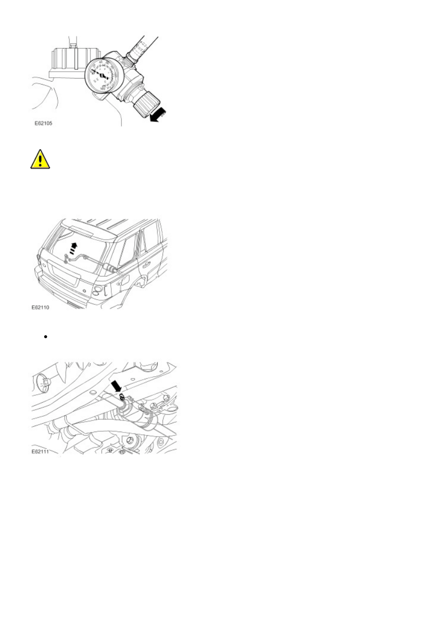
31.  When a steady flow of clean air free fluid is running from the bleed point, tighten the bleed screw to 15 Nm (11 lb.ft). 


Release the switch on the special tool to switch off the actuator control valves. 

32.  Loosen the rear actuator LH bleed screw by one-half of a turn. 

34.  NOTE: 


It may be necessary to operate the switch several times to help pulse the air out of the actuator.

Bleed the dynamic response system until a flow of clean, air-free fluid, is being pumped into the bleed jar. 

35. 

  CAUTION: Move the stabilizer bar in the stated direction of travel only. Failure to follow this instruction may

result in air being drawn back in to the actuator.

With the actuator control valves still open, operate the stabilizer bar downwards through its full travel, to release any trapped
air from the actuator. 

36.  When a steady flow of clean air free fluid is running from the bleed point, tighten the bleed screw to 15 Nm (11 lb.ft). 


Release the switch on the special tool to switch off the actuator control valves. 

37.  Repeat the rear stabilizer bar bleed procedure, from steps 27 to 36, a further two times, to make sure all air is removed
from the actautor. 


Discard the fluid from the bleed jar. 


Install the bleed screw covers. 

39. 

  CAUTION: Use a wrench on the hexagon provided to prevent the ball joint rotating.

LH rear: Connect the stabilizer bar link. 


Install a new nut and tighten to 175 Nm (129 lb.ft). 

40.  Disconnect the special tool from the valve block. 


Connect the valve block electrical connectors. 

41.  Install the wheels and tires. 


Tighten the wheel nuts to 140 Nm (103 lb.ft). 

42. 

  WARNING: The special tool is still pressurised when the source air pressure is removed. Release air

pressure within special tool slowly before removing.

Remove the special tool from the dynamic response system reservoir. 


Remove the special tool. 


Top-up the fluid level to the mid-way mark on the reservoir. 

43.  Using T4, check the operation of the dynamic response system. 

44.  If necessary, repeat the above procedure. 

Ride and Handling Optimization 

Terrain Response - Component Location

Item Part Number

Description

1

 -

Air suspension control module

2

 -

Instrument cluster

3

 -

Terrain Response rotary control and control module

4

 -

Rear differential control module (if fitted)

5

 -

Rear differential

6

 -

Transfer box (center differential and high/low range)

7

 -

Engine control module

8

 -

Transfer box control module

9

 -

Transmission control module (automatic transmission only)

10

 -

ABS module


Content   ..  72  73  74  75   ..