Range Rover Sport. Manual - part 63


  Index      Land Rover     Range Rover Sport - service repair manual 2005-2009 year


Search            


Content   ..  61  62  63  64   ..


Range Rover Sport. Manual - part 63


Remove the air spring.


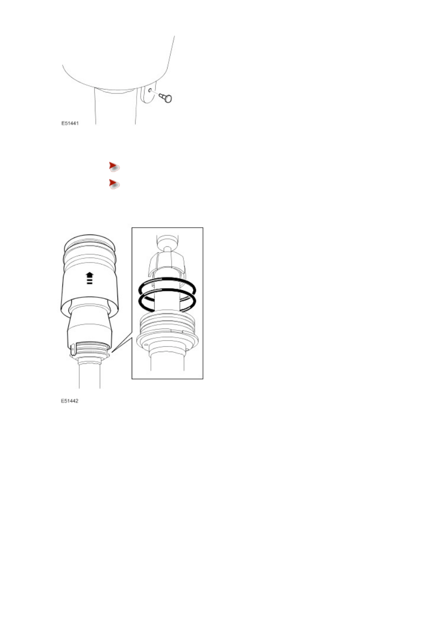
Using a soft faced mallet, gently tap the sleeve support upwards to release it from the O-ring
seals.


Remove and discard the 2 O-ring seals.

6 . Remove the rebound plate and spring aid.

7 . Remove the shock absorber from the vise.

Installation

1 . Install the shock absorber in the vise.

2 . Clean the components.

3 . Lubricate and install new O-rings to the seal carrier.

4 . Install the spring aid and rebound plate.


Align the piston with the first O-ring seal, making sure the location tag is correctly aligned.


Install the new O-ring seals and spacer, taking care not to damage the seals.

6 . Install the rubber bushing and rebound washer.


Make sure the formed insert on the bushing is located against the O-ring seal.


Install and lightly tighten the nut.

7
.

  CAUTION: The air supply must be free of any moisture.

  CAUTION: If during disassembly the air sleeve is unrolled, the air sleeve may inflate incorrectly (to

one side). If this occurs, release the air pressure, and insert a suitable tool that will not damage the air
sleeve or piston (a screw driver handle), into the side opposite the bulge. Inflate and deflate until the air
sleeve inflates correctly (the air sleeve will be uniform inside the shroud).

Using the special tool coupled to a tire inflator with a gauge, apply approximately 2 bar of air pressure to the air
spring to fully seat the piston over the O-ring seals. 

9 . Install a new nut and tighten to 98 Nm (72 lb.ft).

10
.

Check the assembly for leaks.


Inflate the module to 4 bar and check for pressure loss.


If a leak is suspected, immerse the spring and shock absorber assembly in a tank of water
to locate the source of the leak.

11 . Remove the special tool.

12 . Install the shock absorber and spring assembly. 

For additional information, refer to 

Suspension Height Sensor (60.36.01) 

Removal

NOTE: 


The rear height sensors are handed. The right hand sensor has a black colored lever and the left hand sensor has a
white colored lever. The front height sensors are not handed, and are fitted with grey levers for identification.

NOTE: 


This procedure covers removal and installation of both the front and rear suspension height sensors.

1
.

  WARNING: Do not work on or under a vehicle supported only by a jack. Always support the vehicle

on safety stands.

Raise and support the vehicle.

2 . Remove the wheel and tire.

3 .

  CAUTION: Do not use excessive force to disconnect the height sensor link.

Disconnect the height sensor link.

4 . NOTE: 


Front suspension height sensor shown, rear similar.

Remove the suspension height sensor.


Disconnect the electrical connector.


Remove the 2 Torx screws.

Installation

1 . To install, reverse the removal procedure.


Tighten the screws to 2.2 Nm (1.5 lb.ft).

2


Content   ..  61  62  63  64   ..