Range Rover Sport. Manual - part 50


  Index      Land Rover     Range Rover Sport - service repair manual 2005-2009 year


Search            


Content   ..  48  49  50  51   ..


Range Rover Sport. Manual - part 50


Suspension Prevented From Moving

If the air suspension control module is attempting to change the suspension height and it detects that the suspension is
prevented from moving, the control module will stop all suspension movement. This can be caused by jacking the vehicle,
attempting to lower the vehicle onto an object or raising the vehicle against an obstruction.

The air suspension switch lamps operate as described for extended mode and the same message is displayed in the
message center. To start the air suspension system operating, press the air suspension switch briefly in the up or down
position or drive the vehicle at a speed of more than 12.5 mph (20 km/h).

Periodic Re-levelling

When the vehicle is parked, the air suspension control module 'wakes up' two hours after the ignition was last switched off
and then once every six hours. The vehicle height is checked and if the vehicle is not level within a pre-set tolerance, small
downwards height adjustments may be made automatically.

Transportation Mode

Transportation mode is a factory set mode which locks the suspension to enable the vehicle to be safely lashed to a
transporter. Transportation mode can only be selected or deselected using T4.

When the ignition switch is switched off, the vehicle will be lowered onto the bump stops. This ensures that the securing
straps do not become loose should air leak from the air springs.

When the engine is running, the air supply unit will operate to raise the vehicle height, allowing the vehicle to be loaded.
When the ignition switch is subsequently switched off, the vehicle will again lower onto the bump stops. An audible warning
will be emitted from the instrument cluster sounder until the vehicle has reached the higher transportation height.

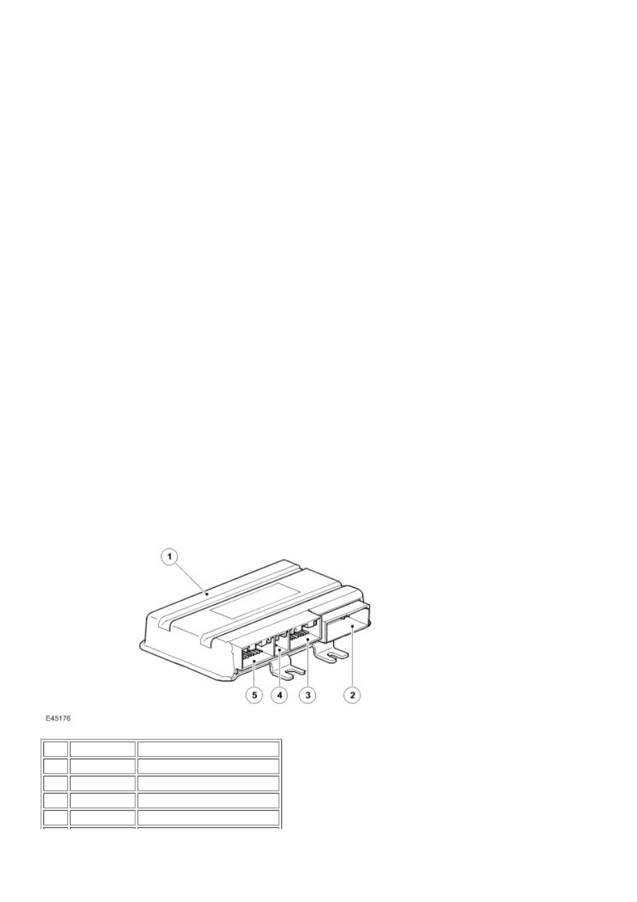
AIR SUSPENSION CONTROL MODULE

Item Part Number

Description

1

 -

Air suspension control module

2

 -

Connector C2321

3

 -

Connector C2320

4

 -

Connector C2030

 -

Connector C0867

The air suspension control module is located behind the instrument panel, on the driver's side 'A' pillar. The control module
is attached to the 'A' pillar with a single screw and two plastic clips.

The air suspension control module also contains the software for the variable steering. For additional information, refer to 

Power Steering

 (211-02 Power Steering)

Calibration

A calibration routine is performed using T4 to access the position of each corner of the vehicle and record the settings in the
control module memory. Once set, the calibration is not required to be performed unless the air suspension control module
is removed or replaced, a height sensor is removed or replaced or a suspension arm to which the sensor is connected is
removed or replaced. If a removed height sensor is subsequently refitted, the calibration procedure will have to be
performed to ensure the integrity of the system.

If the air supply unit, the reservoir, a valve block, a damper module or the air harness is removed or replaced, the system will
not require recalibration.

Inputs and Outputs

The air suspension control module uses four harness connectors for all inputs and outputs.

The air suspension control module uses inputs received on the CAN bus from other vehicle systems. The system uses
longitudinal acceleration, lateral acceleration, steering angle and wheel speed data to control the suspension operation in
differing driving conditions.

The system will react differently if one or more of these data inputs is missing or incorrect, for example, if the steering angle
sensor is missing or incorrect, the air suspension control module assumes a default value of zero which may result in some
unnecessary levelling activity.

Steering - Servotronic Valve

The power steering Servotronic 2 system is controlled by software which is incorporated into the air suspension control
module. The software responds to steering torque inputs and road speed signals and controls the assistance via a
transducer valve located on the steering gear valve. The valve is connected by two wires to the control module on connector
C2320. For details refer to the Power Steering section. For additional information, refer to  

Power Steering

 (211-02 Power

Steering)

Air Supply Unit Relay

The air supply unit relay is located in the Battery Junction Box (BJB) in the engine compartment. The relay is connected
directly to the battery via fusible link 10E (60A). The relay coil is connected to and controlled by the air suspension control
module. The relay is used by the air suspension control module to control the operation of the compressor.

When air supply unit operation is required, the air suspension control module supplies power and ground for the relay coil
which energises, closing the relay contacts. This allows battery voltage via the fusible link to pass through the relay and
operate the air supply unit electric motor and the compressor.

The battery voltage is also passed from the relay, via a splice joint in the harness, to the air suspension control module and
is used as a signal that the air supply unit is operating.

System Inhibits

A number of conditions exist where a change of ride height is undesirable. To counter this, the air suspension control
module is programmed with a number of system inhibits. If any of the conditions detailed below exist, the air suspension
control module will suspend height changes and height corrections.

The temperature sensors located within the compressor protect the compressor from overheating. If the compressor
temperature rises above set limits, the air suspension control module will inhibit the compressor operation. These limits are
shown in the following table:

Compressor Head Temperature Sensor


Lifting

Filling Reservoir

Stop 150°C (302°F)

140°C (284°F)

Start 130°C (266°F)

120°C (248°F)

Compressor Brush Temperature Sensor


Lifting

Filling Reservoir

Stop 140°C (284°F)

130°C (266°F)

Start 120°C (248°F)

110°C (230°F)

Cornering 

If the air suspension control module registers a cornering force greater than 0.2g it will inhibit all height changes and
corrections. The system will remain inhibited until the cornering force falls to less than 0.15g. The air suspension control
module receives a message from the lateral acceleration sensor (which is an integral part of the ABS yaw rate sensor) on
the high speed CAN bus for the cornering force.

Rapid Acceleration 

If the air suspension control module registers a rapid acceleration greater than 0.2g it will inhibit all height changes and
corrections. The system will remain inhibited until the rapid acceleration falls to less than 0.15g. Acceleration is calculated
by the air suspension control module from a vehicle speed signal received via the high speed CAN bus.

Rapid Deceleration 

If the air suspension control module registers a rapid deceleration smaller than -0.2g it will inhibit all height changes and
corrections. The system will remain inhibited until the rapid deceleration rises above -0.15g. Deceleration is calculated by
the air suspension control module from a vehicle speed signal received via the high speed CAN bus.

Vehicle Jack 

The air suspension control module will inhibit all height changes and corrections if it detects a corner lowering too slowly for
more than 1.2 seconds. This is interpreted as the corner identified as moving too slowly being supported on a jack. In this
situation, the corner height will not change when air is released from the air spring because the jack acts as a mechanical
prop. The system will remain inhibited until any of the following conditions exist:

The air suspension switch is moved to the up or down position
Vehicle speed rises to more than 9.3 mph (15 km/h) for more than 15 seconds.

Door Open 

The air suspension control module will stop all height change requests while any of the doors are open. Vehicle levelling
continues with a door open by keeping the vehicle at the height when the door was opened if the vehicle load changes.

Diagnostics

The air suspension control module can store fault codes which can be retrieved using T4. The diagnostic information is
obtained via the diagnostic socket which is located in the lower instrument panel closing panel, on the driver's side, below
the steering column.

Fault Detection 

The air suspension control module performs fault detection and plausibility checks. Fault detection is limited to faults that the
control module can directly measure as follows:

Sensor electrical hardware faults
Valve electrical hardware faults
Sensor and actuator supply faults
Bus failures
Control module hardware errors.

Plausibility checks are checks on signal behaviour, as follows:

Average height does not change correctly Height changes too slowly

Height changes too slowly

Gallery pressure Does not increase fast enough when reservoir filling requested Increases when system is inactive
Too low when lifting is requested Increases too rapidly when filling reservoir Does not decrease when gallery is
vented Pressure varies too much when inactive.

Does not increase fast enough when reservoir filling requested
Increases when system is inactive
Too low when lifting is requested
Increases too rapidly when filling reservoir
Does not decrease when gallery is vented
Pressure varies too much when inactive.

Compressor temperature Sensor voltage too large - head and brush sensors (short circuit to battery) Takes too long
to be readable after suitable compressor run time - head and brush sensors Does not increase when compressor
active - head sensor only

Sensor voltage too large - head and brush sensors (short circuit to battery)
Takes too long to be readable after suitable compressor run time - head and brush sensors
Does not increase when compressor active - head sensor only

Sensor activity Signal floating Constant articulation when moving

Signal floating
Constant articulation when moving

When a fault is detected, the air suspension control module will attempt to maintain a comfortable ride quality and where
possible will retain as much functionality as possible.

The system functionality depends on the severity of the fault.

Faults 

Height sensor faults (hardware faults) and reservoir valve block failure Retain full functionality with no 'refinements',
e.g. cross-link valves inoperative, no compensation for uneven surfaces.

Retain full functionality with no 'refinements', e.g. cross-link valves inoperative, no compensation for uneven
surfaces.

Pressure sensor faults, compressor faults, corner valves stuck shut Road speed signal not available Vehicle returns
to on-road mode height when next requested Levels at 'current' height.

Road speed signal not available
Vehicle returns to on-road mode height when next requested
Levels at 'current' height.

Reservoir valve stuck open, exhaust valve stuck shut if below on-road mode height, corner valves stuck open if
above on-road mode height Vehicle returns to on-road mode height when next requested Does not level at 'current'
height.

Vehicle returns to on-road mode height when next requested
Does not level at 'current' height.

Failure of multiple height sensors, cross-articulation when driving, calibration corrupted Vehicle lowers to bump
stops.

Vehicle lowers to bump stops.

ABS module failure, CAN bus failure If the air suspension control module loses communications with the ABS


Content   ..  48  49  50  51   ..