Range Rover Sport. Manual - part 3


  Index      Land Rover     Range Rover Sport - service repair manual 2005-2009 year


Search            


Content   ..  1  2  3  4  ..


Range Rover Sport. Manual - part 3


Fuel system hoses

All fuel hoses are made up of two laminations, an armored rubber outer sleeve and an inner viton core. Whenever a hose is
removed, ensure that the inner bore is inspected to check that the viton lining has not become separated from the outer
sleeve.

  WARNING: Never attempt to repair fuel foses or rectify leaking 'quick-fit' connectors the fuel hose and

connectors must be replaced as an assembly.

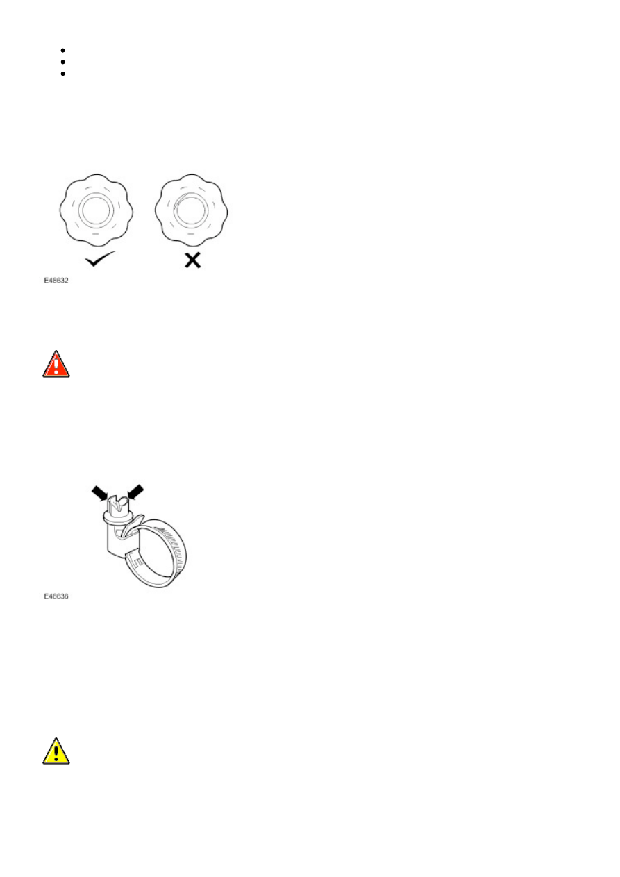
Fuel system hose clips

Certain fuel system hose clips are of the 'break-off head' type where a slot in the screw head shears off when the clip is
tightened to a specific torque. These clips may be removed using a screwdriver and must be replaced with new clips on
reassembly. Clips must be tightened until the portion of the slot shears off. Do not attempt to tighten clips by any other
method, do not fit any other type of clip.

Cooling system hoses

  CAUTION: The following precautions must be observed to ensure that the integrity of the cooling system

hoses and their connection to the system is maintained.

Correct orientation of cooling system hoses is important to ensure that hoses do not become fatigued or damaged through
contact with adjacent components. 

Where orientation marks are provided on the hose and corresponding component, the marks must be aligned when the
hose is fitted. Hoses must be fitted fully on to their connection points, usually a moulded form on a pipe provides a positive
indicator.

Hose clips

Markings are usually provided on the hose to indicate the correct clip position. If no markings are provided, position the clip
directly behind the retaining lip at the end of the stub pipe. Worm drive clips should be orientated with the crimped side of
the drive housing facing towards the end of the hose or the hose may become pinched between the clip and the stub pipe
retaining lip. Unless otherwise stated, worm drive clips should be tightened to 3 Nm (2 lbf.ft). Ensure that hose clips do not
foul adjacent components.

Oetiker clips may be removed by bending the tag (arrowed) and releasing the free end of the clip. Clips must not be reused.
When fitting new clips, ensure clip is positioned on hose before tightening and ensure that when clip is tightened, the tag is
located in the longitudinal slot in the free end of the clip (arrowed in illustration).

Always ensure that heatshields and protective sheathing are in good condition; replace if damage is evident. Particular care
must be taken when routing hoses close to hot engine components such as the exhaust manifolds and exhaust gas
recirculation (EGR) pipes. Hoses will relax and deflect slightly when hot, ensure this movement is taken into account when
routing and securing hoses.

Electrical Precautions

General

The following guidelines are intended to ensure the safety of the operator whilst preventing damage to the electrical and
electronic components of this vehicle.

Equipment

Prior to commencing any test procedure on the vehicle, ensure that the relevant test equipment is working correctly and that
any harness or connectors are in good condition. It is particularly important to check the condition of all plugs and leads of
mains operated equipment.

Polarity

Never reverse connect the vehicle battery and always ensure the correct polarity when connecting test equipment.

High voltage circuits

Whenever disconnecting live ht circuits, always use insulated pliers and never allow the open end of the ht lead to contact
other components, particularly ECU's. 

Vehicles fitted with Bi-Xenon headlamp bulbs

  WARNING: The following precautions must be observed as failure to comply may result in exposure to

ultra-violet rays, severe electric shock, burns or risk of an explosion.

Safety goggles and gloves must be worn.
Ensure that headlamps are switched off before removing bulbs.
Do not touch the glass portion of the bulb.
On no account should headlamps be switched on with the bulb removed from the headlamp.
Bulb testing may only be carried out with the bulb fitted in the headlamp.
Bulbs must be disposed of in accordance with the local authority bye-laws.

Connectors and harnesses

The engine compartment of a vehicle is a particularly hostile environment for electrical components and connectors. Always
observe the following:

Ensure electrically related items are dry and oil free before disconnecting/connecting test equipment.
Ensure that disconnected multiplugs and sensors are protected from any possible oil, coolant or other liquid
contamination. Any such contamination could impair performance or lead to component failure.
Never force connectors apart or pull on the wiring harness.
Always ensure locking tabs are disengaged before disconnecting multiplugs etc. and ensure that correct orientation
is achieved before connection.
Ensure that any protection covers, insulation etc. are replaced if disturbed.

Having confirmed that a component is faulty, carry out the following:

Battery Disconnection/Connection

Always refer to the Electrical Section of this manual - Battery Connection/Disconnection prior to attempting to connect or
disconnect the battery. For additional information, refer to  

Specifications

 (414-00 Charging System - General Information)

Fuel Handling Precautions

The following information lists basic precautions which must be observed if fuel is to be handled safely. It also outlines other
areas of risk which must not be ignored. As this information is issued for basic guidance only, consult your local Fire
Department where any doubt as to personal and environmental safety exists - See also Health and Safety Precautions.

General precautions

Always have the correct type of fire extinguisher containing Foam, CO2, Gas or powder accessible when handling or
draining fuel or dismantling fuel systems. Fire extinguishers must also be located in areas where fuel is stored.

Ensure that suitable warning signs are exhibited.

Keep all sources of ignition well away from areas where fuel is being handled.

Ensure that any leadlamps are flameproof and kept clear of spillage.

  WARNING: Do not disassemble or reassemble fuel system components whilst vehicle is over a pit.

  WARNING: No one should be permitted to repair components associated with fuel without first having

specialist training.

Always disconnect the vehicle battery before carrying out disassembly, reassembly or draining work on a fuel system.

Fuel tank and system draining

Draining must be carried out in accordance with the procedures given in the relevant Fuel System section of this manual.

  WARNING: Never drain fuel or work on a fuel system while the vehicle is over a pit. Extraction or draining

of fuel must be carried out in a well ventilated area.

  WARNING: Always attach fuel vapor warning labels to fuel tanks immediately after draining.

  WARNING: Containers used for storing fuel must be clearly marked with the contents and placed in a safe

storage area which meets the requirements of the local authority.


Content   ..  1  2  3  4  ..