Jeep Renegade (2018 year). Instruction - part 13


  Index      Jeep     Jeep Renegade - instruction 2018 year in english


Search            


Content   ..  11  12  13  14   ..


Jeep Renegade (2018 year). Instruction - part 13


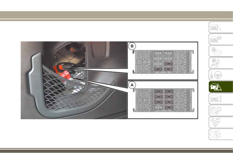
Depending on the car fittings, there could be control unit A and/or control unit B (see fig. 167).
A: fuse holder central unit no.1
B: fuse holder control unit no.2

167

J0A0324C

205

ENGINE COMPARTMENT FUSE BOX

fig. 163

DEVICES

FUSE

AMPERE

Horn

F10

15

Luggage compartment power socket supply

F18

20

Available

F30

Heated door mirrors

F88

7,5

Heated rear window

F89

30

206

IN

AN

EMERGENCY

DASHBOARD FUSE BOX

fig. 165

USERS

FUSE

AMPERE

Front electric window (passenger side)

F33

20

Front electric window (driver side)

F34

20

System power supply

Uconnect™

Climate Control system, Alarm, Electric door mirror folding,
EOBD system, USB port

F36

15

Safe Lock device (Driver side door unlocking - where
provided)/Door unlocking/Central locking/Electric tailgate
unlocking

F38

20

Windscreen/rear window washer pump

F43

20

Rear left electric window

F47

20

Rear right electric window

F48

20

Cigar lighter (where provided)

F94

15

207

LUGGAGE COMPARTMENT FUSE BOX

fig. 167
COMMENT The luggage compartment control unit varies according to the car's equipment.

Fuse holder control unit no. 1

USERS

FUSE

AMPERE

Hi-Fi system

F2

20

Electric sunroof

F3

20

Electric front seat lumbar regulation (driver's side)

F4

7.5

Electric front seat movement (driver's side)

F5

30

Electric front seat movement (driver's and passenger's sides)

F6

7.5

Electric front seat lumbar support (driver's and passenger's
sides)

F7

30

Front seat electric heating

F8

20

In addition, the control unit has a 20A fuse to protect the sunroof panel.

Fuse holder control unit no. 2

USERS

FUSE

AMPERE

Control unit for external light control on trailer

F1

10

Control unit for external lights (left side)

F5

15

Control unit for external lights (right side)

F6

15

208

IN

AN

EMERGENCY

WARNING

154) If the replaced fuse blows again,
contact a Jeep Dealership.
155) Never replace a fuse with another
with a higher amp rating; DANGER OF
FIRE.
156) If a general fuse (MAXI-FUSE,
MEGA-FUSE, MIDI-FUSE) cuts in, do not
attempt any repair and contact a Jeep
Dealership.
157) Before replacing a fuse, make sure
that the ignition device is at STOP, that
the key, if mechanical, has been removed
and that all devices are switched off
and/or disconnected.
158) If a general protection fuse for safety
systems (airbag system, braking system),
power unit systems (engine system,
transmission system) or steering system
blows, contact a Jeep Dealership.

IMPORTANT

77) Never replace a fuse with metal wires
or anything else.
78) If it is necessary to wash the engine
compartment, take care not to directly hit
the fuse box and the window wiper motors
with the water jet.

CHANGING A WHEEL

159) 160) 161) 162) 163) 166) 167)

JACK

164) 165)

Please note that:

the weight of the jack is 2.8 kg;
the jack requires no adjustment;
the jack cannot be repaired and in the

event of a fault it must be replaced by
another genuine one;

no tool other than its cranking device

may be fitted on the jack.

Maintenance

prevent any dirt from depositing on

the "worm screw";

keep the "worm screw" lubricated;
never modify the jack.

Conditions for non-use

temperatures below −40°C;
on sandy or muddy ground;
on uneven ground;
on steep roads;
in extreme weather conditions:

thunderstorms, typhoons, hurricanes,
blizzards, storms, etc...

in direct contact with the engine or for

repairs under the car;

on boats.

209

CHANGING PROCEDURE

Proceed as follows:

stop the car in a position that does

not cause any danger to traffic and lets
you change the tire in safety, as far as
possible from the edge of the driving
lane. The ground must be flat and
sufficiently compact;

engage the hazard warning lights and

the electric parking brake;

engage first gear or reverse or, for

versions with automatic transmission,
move the lever to position P (Park);

stop the engine and put on the

reflective safety jacket (for your own
safety and in compliance with national
laws) before getting out of the vehicle.
The motor must be kept off as long as
the car is lifted off the ground.
The spare tire, or depending on the
version, the temporary spare tire, are
located under the covering carpet in the
boot fig. 168.

To access the tire or spare tire, proceed
as follows:

open the boot door, grab device A

fig. 169 and lift load platform B up,
holding it with one hand;

grab handle C fig. 170 and lift up the

covering carpet;

168

J0A0338C

169

J0A0284C

170

J0A0365C

210

IN

AN

EMERGENCY

remove the spare tire jack's attaching

device;

remove the wheel block wedge;

remove the jack and the spanner to

dismount the spare tire bolt. Turn the
jack's screws to loosen the spanner and
separate it from the jack mechanism;

remove the tire from the boot.

Tool kit bag (where there is one)

On the versions with a spare tire, inside
the boot (on the right side) there is a tool
kit latched to the boot's covering carpet
with its own attachments.
Inside the tool kit there are fig. 171:

A: the jack;
B: the screwdriver;
C: the refuelling adaptor in case of

emergency;

D: the pin to centre to wheel (where

there is one, use it when mounting the
spare tire);

E: a special anti-theft bolt (where

present, use when mounting/dismounting
the tire bolt);

F: a wedge to block the wheel;
G: the towing ring;

H: the spanner for mounting/locking

the tire bolt and to work the jack;

I: the emergency allen key to activate

the sunroof (where there is one).

Important information about the jack

Please note that:

the whole jack weighs 2.8kg;
the jack requires no adjustment;

the jack cannot be repaired: if it

breaks, it must be replaced with another
original;

no tool, except the crank wheel, can

be attached to the jack.
Proceed as follows:

in case where you have to place the

car on an inclined roadway, if it is very
steep, or if the ground is unstable, lift
out the blocking wedge A and open it like
a book, as shown in the illustration
fig. 172;

warn anyone present that the car is

going to be lifted up: they need to leave
the immediate vicinity and even more
important, warn them not to touch the
car until it has been brought back down.

171

J0A0226C

172

J0A0157C

211

No one should remain inside the car;

if the car has alloy rims, whose

hubcaps cover the bolt, use the spanner
very carefully to remove the hubcap
before lifting the car up;

before lifting up the car, loosen the

bolts on the wheel with the flat tire
without removing them, using spanner A
fig. 173. While the tire is still resting on
the ground, you just need to turn the
bolts one turn counter-clockwise;

position the jack under the car, near

the tire to be changed;

insert the spanner D fig. 174 on the

hexagon A of the jack B and turn it
clockwise until the jack bracket is firmly
under the area to be lifted, at the spar
under the door, being careful to keep it

in line with the bracket itself at the mark
indicated by the symbol

on the under

door coating;

lift up the car until the tire is off the

ground by a few centimetres;

remove the bolt and the tire (for

versions equipped with a tire cover, take
it off after having loosened the 4 bolts
that attach it and then unscrew the last
bolt and remove the tire);

remove the jack spanner and insert

the pin to centre the wheel (in case of
alloy rims) to facilitate mounting the
spare tire;

make sure the spare tire, where it

comes into contact with the centre, is
clean and has no debris that could later
cause the attachment bolts to loosen;

mount the spare tire;
replace and screw the bolts, without

tightening them;

if you used it, remove the aligning

pin;

lower the car completely using the

jack.

take the spare wheel, jack and wheel

bolt removal key (see fig. 171 );

if the vehicle has aluminium rims,

where the hub cap covers the bolts, use
the key with great care to remove the hub
cap before raising the vehicle;

tighten the bolts, alternating from one

bolt to the one opposite, according to the
numerical sequence illustrated in
fig. 175. In the case of any doubts
regarding the bolt tightening torque,
contact a Jeep Dealership;

reposition the jack, the tools, the

chock and the flat tyre inside the luggage

173

J0A0249C

174

J0A0422C

212

IN

AN

EMERGENCY

compartment, ensuring that they are
locked correctly.

IMPORTANT

Should it be absolutely necessary to

operate on the road surface or near it,
pay the utmost attention to vehicles in
transit.

Pay particular attention when using

the key to remove the bolts: it may have
sharp edges.

Raising the vehicle any more than

necessary may lower its stability: the jack
may slip and injure those nearby. Do not
raise the vehicle any more than required
for the removal of the wheel.

Tyres with unidirectional tread can be

recognised by arrows on the side of the
tyre which indicate the direction of

rotation. This must of necessity be
complied with. Only in this way can the
tyres maintain their characteristics in
terms of grip, noise, resistance to wear
and drainage on wet surfaces.

If, after a puncture, it is necessary to

fit such a tyre the wrong way round, it
will be necessary to continue driving with
great care, since the tyre’s performance
is limited in these conditions. This
precaution must be borne in mind above
all when the road surface is wet.

In order to benefit completely from

the unidirectional tread, it is advisable to
restore all wheels to the correct direction
of rotation as soon as possible.

Make sure that the spare wheel is

fitted with the valve facing outwards. The
wheel may be damaged if fitted
incorrectly.

If the vehicle has a hub cap or wheel

cover, do not attempt to fit it on the
spare wheel.

To prevent injury to persons, the

complete tightening of the bolts must
only be carried out when all of the
vehicle’s wheels are on the ground, to
prevent the vehicle falling from the jack.

After having travelled for about

40 km, stop and check that the bolts are
tightened correctly.

WARNING

159) If left in the passenger compartment,
the punctured wheel and jack constitute a
serious risk to the safety of occupants in
the event of accidents or sharp braking.
Therefore, always place both the jack and
punctured wheel in the dedicated housing
in the luggage compartment.
160) It is extremely dangerous to attempt
to change a wheel on the side of the
vehicle next to the driving lane: make sure
that the vehicle is at a sufficient distance
from the road, to avoid being run over.
161) Alert other drivers that the car is
stationary in compliance with local
regulations: hazard warning lights,
warning triangle, etc. Any passengers on
board should leave the car, especially if it
is heavily laden. Passengers should stay
away from on-coming traffic while the
wheel is being changed. On slopes or on
unsurfaced roads, chock the wheels with
the chocks provided.

175

J0A0159C

213

214

IN

AN

EMERGENCY

162) The vehicle's driving characteristics
will be modified with the space-saver
wheel fitted. Avoid violent acceleration
and braking, abrupt steering and fast
cornering. The overall duration of the
space-saver wheel is about 3000 km, after
which the relevant tyre must be replaced
with another one of the same type. Never
install a standard tyre on a rim that is
designed for use with a space-saver wheel.
Have the wheel repaired and refitted as
soon as possible. Using two or more
space-saver wheels at the same time is
forbidden. Do not grease the threads of
the stud bolts before fitting them: they
might slip out when driving!

163) The space-saver wheel (where
provided) is specific to your vehicle: do
not use it on other models, or use the
space-saver wheel of other models on your
vehicle. The space-saver wheel must only
be used in the event of an emergency.
Never use it for more than strictly
necessary and never exceed 80 km/h. On
the space-saver wheel there is an orange
label, summarising the main warnings
regarding space-saver wheel usage
restrictions. Never remove or cover the
label. Never apply a wheel cap on a
space-saver wheel.

164) The jack is a tool developed and
designed only for changing a wheel, if a
tyre gets punctured or damaged, on the
vehicle with which it is supplied or on
other vehicles of the same model. Any
other use, e.g. to jack up other vehicle
models or different things, is strictly
prohibited. Never use it to carry out
servicing or repairs under the vehicle or to
change summer/winter wheels and vice
versa: we advise you to contact a Jeep
Dealership. Never go under the raised
vehicle: use it only in the positions
indicated. Do not use the jack for loads
higher than the one shown on its label.
Never start the engine with car raised. If
the vehicle is raised more than necessary,
everything can become more unstable,
with the risk of the vehicle dropping
violently. Thus, lift the car only as needed
in order to access the space-saver spare
wheel.

165) When turning the jack handle make
sure that it can turn freely without
scraping your hand against the ground.
The moving components of the jack
("worm screw" and joints) can also cause
injuries: do not touch them. If you come
into contact with lubricating grease, clean
yourself thoroughly.

166) The space-saver wheel cannot be
fitted with snow chains. If a front (drive)
tyre is punctured and chains are needed,
use a standard wheel from the rear axle
and install the space-saver wheel on the
rear axle. In this way, with two normal
drive wheels at the front axle, it is
possible to use snow chains.

167) Incorrect hub cap assembly, if
present, may cause it to come off when
the vehicle is moving. Never tamper with
the inflation valve. Never introduce tools
of any kind between the rim and the tyre.
Check tyre and space-saver wheel
pressures regularly, complying with the
values given in the "Technical
specifications" chapter.

TIREKIT

(where provided)

DESCRIPTION

168) 169)

79)

3)

The TireKit is located in the luggage
compartment inside its own box. The
container is also equipped with a
screwdriver, the tow ring and the
refuelling adaptor.

LPG versions

The car has a “TireKit” quick tyre repair
kit, not a space-saver spare wheel,
located in the boot inside a specific rigid
preformed housing fig. 176.

The TireKit fig. 177 comprises:

one cartridge A containing sealant and

fitted with: transparent tube for injecting
the sealant and sticker C with the
wording MAX 80 km/h / 50 mph to be
placed in a clearly visible position (e.g.
on the dashboard) after repairing the
tyre;

one compressor B;
one leaflet containing instructions for

using the kit;

a pair of gloves located in the hose

compartment of the cartridge D.

REPAIR PROCEDURE

Proceed as follows:

stop the car in a position that is not

dangerous for oncoming traffic where you
can change the wheel safely. The car
must be stopped in a lay-by, car-park or
parking or service area, and the ground
must be as level as possible and
sufficiently compact;

switch off the engine, apply the

electrical parking brake and engage the
1st gear or reverse gear. Make sure that
any passengers get out of the car and go
to a safe place where they will not
obstruct traffic or be exposed to the risk
of injury. Wear the reflective safety jacket
(compulsory by law) before getting out of
the car;

176

J0A0947C

177

J0A0955C

215

insert the cartridge A containing the

sealant in the proper compartment of the
compressor B, pressing it down hard.
Remove the adhesive speed label C and
apply it in a visible position;

wear the gloves;
remove the cap from the tyre valve and

connect and screw the transparent tube
of the sealing fluid D onto the valve. If a
250 ml cartridge is present the housing
of the transparent tube is provided with
removable ring to facilitate extraction.
Make sure that the ON-OFF button F is in
the off position (button not pressed);

insert the electrical connector E

fig. 178 in the 12 V current socket of the
car and start the engine;

operate the compressor by pressing

the ON-OFF button F fig. 179. When the
pressure shown in the "Wheels"
paragraph in the “Technical data”
chapter or on the specific label appears
on the pressure gauge G, stop the
compressor by pressing the ON-OFF
button again;

disconnect the cartridge A

fig. 180 from the compressor, by
pressing the release button H and lifting
the cartridge upwards.

If the pressure gauge G
fig. 179 indicates a pressure lower than
1.8 bar / 26 psi 15 minutes after starting
the compressor, switch off the
compressor, disconnect the sealing fluid
tube D from the tyre valve and remove
the cartridge A from the compressor.
Move the car by approximately 10 metres
to allow the distribution of the sealant.
Stop the vehicle safely, operate the
handbrake and restore pressure using the
black inflation pipe L fig. 181 to reach
the required pressure. If also in this
case, the pressure is lower than 1.8 bar /
26 psi 15 minutes after turning on, do
not resume driving but contact a Jeep
Dealership. After driving for about 8 km /
5 miles fig. 182, move the car to a safe
and suitable area and engage the

ON

OFF

12V

E

178

J0A0956

179

J0A0957

A

H

180

J0A0958

216

IN

AN

EMERGENCY

handbrake. Take the compressor and
restore pressure using the black inflation
tube L.

If the pressure shown is higher than

1.8 bar / 26 psi, restore the pressure and
drive safely to a Jeep Dealership as soon
as possible. If, however, the pressure is
lower than 1.8 bar / 26 psi, do not
resume driving but contact a Jeep
Dealership.

INFLATION PROCEDURE

Proceed as follows:

stop the car safely, as described

above, and operate the electric
handbrake;

extract the black inflation tube and

screw it firmly onto the tyre valve. Then
follow the instructions below. Press the
air release button M to adjust any
excessive tyre pressure (see "Repair
procedure" paragraph).

CARTRIDGE REPLACEMENT

Proceed as follows:

only use original cartridges, which can

be purchased from the Jeep Dealership;

to remove the cartridge, press the

release button and lift it (see description
above).

WARNING

168) IMPORTANT: Do not exceed
80 km/h. Avoid sudden acceleration or
braking. The kit provides a temporary
repair, therefore the tyre must be
examined and repaired by a specialist as
soon as possible. Before using the kit,
ensure that the tyre is not excessively
damaged and that the rim is in good
condition, otherwise do not use it and call
roadside assistance. Do not remove
foreign bodies from the tyre. Do not let the
compressor turned on for more than
20 consecutive minutes - overheating
hazard.
169) The information required by the
applicable regulation is indicated on the
Fix&Go kit package label. Carefully read
the label on the cartridge before use,
avoid improper use. The kit should be
used by adults and cannot be used by
children.

L

181

J0A0959

8 km / 5 mi

182

J0A0960

217

IMPORTANT

79) The sealant is effective with external
temperatures of between -40°C and
+55°C. The sealant has an expiry date. It
is possible to repair tyres which have been
damaged on tread up to a diameter of
6 mm. Show the cartridge and the label to
the personnel charged with handling the
tyre treated with the tyre repair kit.

IMPORTANT

3) Dispose of the bottle and the sealant
liquid properly. Have them disposed of in
compliance with national and local
regulations.

JUMP STARTING

If the battery is flat, a jump starting can
be performed using the battery and the
cables of another vehicle, or using a
booster battery.

IMPORTANT

When using booster battery is used,
comply with the utilisation and
precaution instructions specified by the
producer.
Do not use the booster battery or any
other source of external supply with a
voltage above 12 V: the battery, the
starter, the alternator and the electrical
system of the vehicle could be damaged.
Do not attempt jump starting if the
battery is wet. The battery could break
and explode!

PREPARATION TO JUMP
STARTING

170) 171) 172)

80)

IMPORTANT The positive terminal (+)
of the battery is shielded by a
protective cover. Lift the cover to
access the positive terminal.

Proceed as follows:

operate the parking brake, move the

automatic transmission lever to P (Park)

or, for versions with manual gearbox, to
neutral and bring the ignition device to
STOP;

switch off all the other electrical

appliances in the vehicle;

if another vehicle is ready for

emergency starting, park the vehicle
within the reach of the cables to be used
for starting, operate the parking brake
and make sure that the ignition is
deactivated.

IMPORTANT Avoid contact between
the two vehicles since this could cause
a connection to earth and may result in
serious injury to any people nearby.

PROCEDURE FOR JUMP
STARTING

IMPORTANT If the procedure below is
carried out incorrectly can cause
severe injuries to people or damage the
recharging system of one or both
vehicles. Carefully follow the
instructions given below.

Cable connection

Proceed as follows to carry out a jump
starting:

connect one end of the cable used for

positive (+) to the positive terminal (+) of
the vehicle with flat battery;

218

IN

AN

EMERGENCY

connect the other end of the cable

used for positive (+) to the positive
terminal (+) of the auxiliary battery;

connect one end of the cable used for

negative (–) to the negative terminal (–)
of the auxiliary battery;

Connect the other end of the cable

used for negative (–) to an engine earth
(the visible metal part of the vehicle
engine with flat battery) away from the
battery and the fuel injection system;

start the vehicle engine with the

auxiliary battery, let it run for a few
minutes at idling. Start the engine of the
vehicle with flat battery.

Cable disconnection.

Once the engine has been started,
remove the cables proceeding as follows:

disconnect the end of the cable used

for negative (–) from the engine earth of
the vehicle with flat battery;

disconnect the other end of the cable

used for negative (–) to the negative
terminal (–) of the auxiliary battery;

disconnect the end of the cable used

for positive (+) to the positive terminal
(+) of the auxiliary battery;

disconnect one end of the cable used

for positive (+) from the positive terminal
(+) of the vehicle with flat battery;
If it is often necessary to perform an
emergency starting, have the vehicle

battery and the recharging system
checked by a Jeep Dealership.

IMPORTANT Any accessories (e.g.
mobile phones, etc.) connected to the
vehicle current sockets, draw current
even if they are not used. These
devices, if left connected too much
time with engine off, may cause the
battery to drain with following
reduction of its life and/or failure to
start the engine.

WARNING

170) Do not get too close to the radiator
cooling fan: the electric fan may start;
danger of injury. Scarves, ties and other
loose clothing might be pulled by moving
parts.
171) Remove any metal objects (e.g.
rings, watches, bracelets), that might
cause an accidental electrical contact and
cause serious injury.
172) The batteries contain acid that can
burn skin or eyes. Batteries produce
hydrogen, which is easily flammable and
explosive. Thus keep away flames or
devices which may cause sparks.

IMPORTANT

80) Do not connect the cable to the
negative terminal (–) of the flat battery.
The following spark could lead to battery
explosion and cause serious harm. Only
use the specific earth point; do not use
any other exposed metallic part.

219

FUEL CUT-OFF SYSTEM

173)

This intervenes in the case of an impact
causing:

the interruption of the fuel supply with

the engine consequently cutting out;

the automatic unlocking of the doors;
turning on the lights inside the car;
deactivation of climate control system

ventilation;

switching on the hazard warning lights

(to disable the lights, perform the “reset”
procedure as described below).
On some versions, the intervention of the
system is indicated by a message shown
on the display. In the same way, a
dedicated message on the display warns
the driver if system operation is
compromised.

IMPORTANT Carefully check the
vehicle for fuel leaks, for instance in
the engine compartment, under the
vehicle or near the tank area. After a
collision, bring the ignition device to
STOP to prevent the battery from
running down.

Reset procedure

To restore correct operation of the
vehicle, carry out the following procedure

(this procedure must be started and
completed within less than one minute):

bring the ignition device to MAR;
turn on the direction indicators on the

right, then on the left, then again on the
right and again on the left;

now deactivate the direction indicators

on the left;

bring the ignition device to STOP;
move the ignition device to MAR.

LPG versions

In case of collision, the petrol feed is
immediately closed, the LPG safety
solenoid valves are closed and injection
is interrupted to stop the engine.

WARNING

173) If, after an impact, you smell fuel or
notice leaks from the fuel system, do not
reactivate the system to avoid the risk of
fire.

AUTOMATIC
TRANSMISSION GEAR
LEVER UNLOCKING

In the event of a fault, to move the gear
lever from P (Park), proceed as follows:

stop the engine and engage the

electric parking brake;

Left hand drive versions: lift up the

transmission gaiter A fig. 183 to access
hole B fig. 184. Right hand drive
versions
: lift up the transmission gaiter A
fig. 183 and then remove the badge ,
pulling it from the inside with both hands
(you can access the badge once the
gaiter has been lifted up) to access hole
B fig. 184;

183

J0A0963C

220

IN

AN

EMERGENCY


Content   ..  11  12  13  14   ..