Jeep XJ. Manual - part 634


  Index      Jeep     Jeep XJ - service repair manual 2001 year


Search            


Content   ..  632  633  634  635   ..


Jeep XJ. Manual - part 634


Symptom:

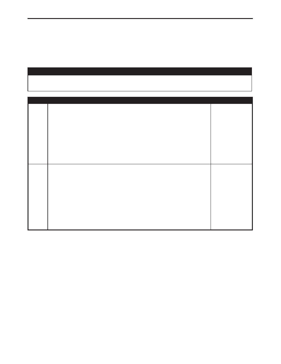
*CHECKING THE FUEL TEMPERATURE SENSOR CALIBRATION

POSSIBLE CAUSES

FUEL TEMPERATURE SENSOR - COLD

FUEL TEMPERATURE SENSOR - HOT

TEST

ACTION

APPLICABILITY

1

Disconnect the Fuel Heater harness connector.
With the DRB, monitor the engine coolant temperature and fuel temperature.
Start and idle the engine until engine temperature reaches 70°C (160°F).
NOTE: If the engine temperature is above 70°C (160°F), allow the engine to
cool down to 70°C (160°F).
Is the fuel temperature between 20°C (70°F) and 50°C (120°F)?

All

Yes

Go To

2

No

Replace the Fuel Injection Pump Assembly in accordance with the
Service Information.
Perform ROAD TEST VERIFICATION - VER-2.

2

Disconnect the Fuel Heater harness connector.
With the DRB, monitor the engine coolant temperature and fuel temperature.
Start and idle the engine until engine temperature reaches 70°C (160°F).
NOTE: If the engine temperature is above 70°C (160°F), allow the engine to
cool down to 70°C (160°F).
Start the engine and allow engine to reach operating temperature of 90°C (195°F).
Does the Fuel Temperature increase smoothly to 40-60°C (100-140°F)?

All

Yes

Test Complete.

No

Replace the Fuel Injection Pump Assembly in accordance with the
Service Information.
Perform ROAD TEST VERIFICATION - VER-2.

188

DRIVEABILITY - DIESEL

Symptom:

*CHECKING THE GLOW PLUG LAMP OPERATION

POSSIBLE CAUSES

ACTUATE THE GLOW PLUG LAMP WITH THE DRB

MESSAGE CENTER - LAMP NEVER ON

MESSAGE CENTER - LAMP ON CONTINUOUSLY

ENGINE CONTROL MODULE - FAILS TO ACTIVATE LAMP

ENGINE CONTROL MODULE - LAMP ON CONTINUOUSLY

GLOW PLUG LAMP CONTROL CIRCUIT SHORTED TO GROUND

GLOW PLUG LAMP CONTROL CIRCUIT SHORTED TO VOLTAGE

GLOW PLUG LAMP CONTROL CIRCUIT OPEN

MESSAGE CENTER IGNITION FEED OPEN

GLOW PLUG LAMP BULB

TEST

ACTION

APPLICABILITY

1

Turn the ignition on and observe the Glow Plug Lamp.
Did the Glow Plug Lamp illuminate and stay on longer than 20 seconds?

All

Yes

Go To

2

No

Go To

4

2

Turn the ignition off.
Disconnect the ECM harness connectors.
Turn the ignition on.
Is the Glow Plug Lamp on?

All

Yes

Go To

3

No

Replace and program the Engine Control Module in accordance
with the Service Information.
Perform ROAD TEST VERIFICATION - VER-2.

3

Turn the ignition off.
Disconnect the PCM harness connectors.
Disconnect the ECM harness connectors.
Measure the resistance between ground and the Glow Plug Lamp Control circuit.
Is the resistance above 100 kohms?

All

Yes

Replace the Message Center.
Perform ROAD TEST VERIFICATION - VER-2.

No

Repair the Glow Plug Lamp Control circuit for a short to ground.
Perform ROAD TEST VERIFICATION - VER-2.

4

Turn the ignition on.
With the DRB, actuate the Glow Plug Lamp.
Does the Glow Plug Lamp cycle on and off?

All

Yes

The Glow Plug Lamp System is operating properly. Test complete.
Perform ROAD TEST VERIFICATION - VER-2.

No

Go To

5

189

DRIVEABILITY - DIESEL

TEST

ACTION

APPLICABILITY

5

Turn the ignition off.
Disconnect the ECM harness connectors.
Turn the ignition on.
Connect a jumper wire between ground and the Glow Plug Lamp Control circuit in
the ECM C1 harness connector.
Is the Glow Plug Lamp on?

All

Yes

Replace and program the Engine Control Module in accordance
with the Service Information.
Perform ROAD TEST VERIFICATION - VER-2.

No

Go To

6

6

Turn the ignition off.
Disconnect the ECM harness connectors.
Disconnect the Message Center harness connector.
Remove the ASD/Diesel Power Relay from the PDC.
Connect a jumper wire between ASD/Diesel Power Relay connector cavities 30 and 87
(in PDC).
Turn the ignition on.
Measure the voltage of the Glow Plug Lamp Control circuit.
Is the voltage below 0.5 volt?

All

Yes

Go To

7

No

Repair the Glow Plug Lamp Control circuit for a short to voltage.
Perform ROAD TEST VERIFICATION - VER-2.

7

Turn the ignition off.
Disconnect the ECM harness connectors.
Disconnect the Message Center harness connector.
Measure the resistance of the Glow Plug Lamp Control circuit.
Is the resistance below 5.0 ohms?

All

Yes

Go To

8

No

Repair the Glow Plug Lamp Control circuit for an open.
Perform ROAD TEST VERIFICATION - VER-2.

8

Turn the ignition off.
Disconnect the Message Center harness connector.
Turn the ignition on.
Measure the voltage of the Ignition Feed circuit.
Is the voltage above 10.0 volts?

All

Yes

Go To

9

No

Repair the Ignition Feed circuit to the Message Center for an
open.
Perform ROAD TEST VERIFICATION - VER-2.

9

Turn the ignition off.
Remove and inspect the Glow Plug Lamp bulb from the Message Center.
Is the bulb OK?

All

Yes

Replace the Message Center.
Perform ROAD TEST VERIFICATION - VER-2.

No

Replace the Glow Plug Lamp bulb.
Perform ROAD TEST VERIFICATION - VER-2.

190

DRIVEABILITY - DIESEL

*CHECKING THE GLOW PLUG LAMP OPERATION —

Continued

Symptom:

*CHECKING THE GLOW PLUG OPERATION

POSSIBLE CAUSES

CHECKING THE GLOW PLUGS

FUSED B+ CIRCUIT OPEN

GLOW PLUG RELAY

GLOW PLUG RELAY OUTPUT CIRCUIT OPEN

TEST

ACTION

APPLICABILITY

1

Turn the ignition off.
Disconnect all four Glow Plug connectors.
Turn the ignition on.
With the DRB, actuate Glow Relay #1.
Using a 12-volt test light connected to ground, probe each Glow Plug connector.
Does the test light cycle on and off for each Glow Plug connector during actuator test?

All

Yes

Go To

2

No

Go To

3

2

Refer to the Service Information and perform the Glow Plug Test.
Are all the Glow Plugs operating properly?

All

Yes

Test Complete.

No

Replace the Glow Plug(s) as necessary in accordance with the
Service Information.
Perform ROAD TEST VERIFICATION - VER-2.

3

Remove the Glow Plug Relay from the PDC.
Turn the ignition on.
Using a 12-volt test light connected to ground, check the Fused B+ circuit in the Glow
Plug Relay connector in the PDC.
Is the test light on?

All

Yes

Go To

4

No

Repair the Fused B+ circuit for an open.
Perform ROAD TEST VERIFICATION - VER-2.

4

Turn the ignition off.
Disconnect all the Glow Plug connectors.
Remove the Glow Plug Relay from the PDC.
Connect a jumper wire across the Glow Plug Relay connector cavities 30 and 87.
Using a 12-volt test light connected to ground, check each Glow Plug Relay Output
circuit at each Glow Plug connector.
Is the test light on at each of the Glow Plug connectors?

All

Yes

Replace the Glow Plug Relay.
Perform ROAD TEST VERIFICATION - VER-2.

No

Repair the Glow Plug Relay Output circuit for an open.
Perform ROAD TEST VERIFICATION - VER-2.

191

DRIVEABILITY - DIESEL


Content   ..  632  633  634  635   ..