Jeep XJ. Manual - part 512


  Index      Jeep     Jeep XJ - service repair manual 2001 year


Search            


Content   ..  510  511  512  513   ..


Jeep XJ. Manual - part 512


is replaced, the refrigerant oil must be drained from
the old compressor and measured. Drain all of the
refrigerant oil from the new compressor, then fill the
new compressor with the same amount of refrigerant
oil that was drained out of the old compressor.

REFRIGERANT RECOVERY

WARNING: REVIEW THE WARNINGS AND CAU-
TIONS IN THE GENERAL INFORMATION SECTION
NEAR THE FRONT OF THIS GROUP BEFORE
RECOVERING REFRIGERANT.

A R-134a refrigerant recovery/recycling/charging

station that meets SAE Standard J2210 must be
used to recover the refrigerant from an R-134a refrig-
erant system. Refer to the operating instructions sup-
plied by the equipment manufacturer for the proper
care and use of this equipment.

REFRIGERANT SYSTEM EVACUATE

WARNING: REVIEW THE WARNINGS AND CAU-
TIONS IN THE GENERAL INFORMATION SECTION
NEAR THE FRONT OF THIS GROUP BEFORE EVAC-
UATING THE SYSTEM.

If the refrigerant system has been open to the

atmosphere, it must be evacuated before the system
can be charged. If moisture and air enters the system
and becomes mixed with the refrigerant, the com-
pressor head pressure will rise above acceptable
operating levels. This will reduce the performance of
the air conditioner and damage the compressor.
Evacuating the refrigerant system will remove the
air and boil the moisture out of the system at near
room temperature. To evacuate the refrigerant sys-
tem, use the following procedure:

(1) Connect a R-134a refrigerant recovery/recy-

cling/charging station that meets SAE Standard
J2210 and a manifold gauge set to the refrigerant
system of the vehicle.

(2) Open the low and high side valves and start

the charging station vacuum pump. When the suc-
tion gauge reads 88 kPa (26 in. Hg.) vacuum or

greater, close all of the valves and turn off the vac-
uum pump.

(a) If the refrigerant system fails to reach the

specified vacuum, the system has a leak that must
be corrected. See Refrigerant System Leaks in the
Diagnosis and Testing section of this group for the
procedures.

(b) If the refrigerant system maintains the spec-

ified vacuum for five minutes, restart the vacuum
pump, open the suction and discharge valves and
evacuate the system for an additional ten minutes.
(3) Close all of the valves, and turn off the charg-

ing station vacuum pump.

(4) The refrigerant system is now ready to be

charged with R-134a refrigerant. See Refrigerant
System Charge in the Service Procedures section of
this group.

REFRIGERANT SYSTEM CHARGE

WARNING: REVIEW THE WARNINGS AND CAU-
TIONS IN THE FRONT OF THIS GROUP BEFORE
CHARGING THE REFRIGERANT SYSTEM.

After the refrigerant system has been tested for

leaks and evacuated, a refrigerant charge can be
injected into the system. See Refrigerant Charge
Capacity for the proper amount of the refrigerant
charge.

A R-134a refrigerant recovery/recycling/charging

station that meets SAE Standard J2210 must be
used to charge the refrigerant system with R-134a
refrigerant. Refer to the operating instructions sup-
plied by the equipment manufacturer for proper care
and use of this equipment.

REFRIGERANT CHARGE CAPACITY

The R-134a refrigerant system charge capacity for

this vehicle is 0.567 kilograms (1.25 pounds).

REFRIGERANT SYSTEM SERVICE EQUIPMENT

WARNING: EYE PROTECTION MUST BE WORN
WHEN SERVICING AN AIR CONDITIONING REFRIG-
ERANT SYSTEM. TURN OFF (ROTATE CLOCKWISE)
ALL VALVES ON THE EQUIPMENT BEING USED,
BEFORE CONNECTING TO OR DISCONNECTING
FROM THE REFRIGERANT SYSTEM. FAILURE TO
OBSERVE THESE WARNINGS MAY RESULT IN PER-
SONAL INJURY.

When servicing the air conditioning system, a

R-134a refrigerant recovery/recycling/charging sta-
tion that meets SAE Standard J2210 must be used.
Contact an automotive service equipment supplier for
refrigerant

recovery/recycling/charging

equipment.

Refer to the operating instructions supplied by the

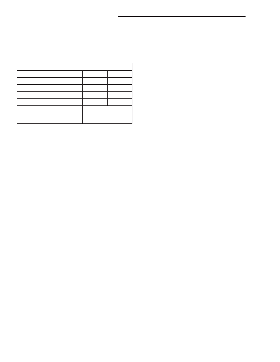
Refrigerant Oil Capacities

Component

ml

fl oz

A/C System

180

6.1

Accumulator

90

3

Condenser

22

.75

Evaporator

45

1.5

Compressor

drain and measure
the oil from the old
compressor as noted

24 - 22

HEATING AND AIR CONDITIONING

XJ

SERVICE PROCEDURES (Continued)

equipment manufacturer for proper care and use of
this equipment.

A manifold gauge set may be needed with some

recovery/recycling/charging equipment (Fig. 13). The
service hoses on the gauge set being used should
have manual (turn wheel), or automatic back-flow
valves at the service port connector ends. This will
prevent refrigerant from being released into the
atmosphere.

MANIFOLD GAUGE SET CONNECTIONS

CAUTION: Do not use an R-12 manifold gauge set
on an R-134a system. The refrigerants are not com-
patible and system damage will result.

LOW PRESSURE GAUGE HOSE The low pressure

hose (Blue with Black stripe) attaches to the suction
service port. This port is located on the suction line
between the accumulator outlet and the compressor.

HIGH PRESSURE GAUGE HOSE The high pres-

sure hose (Red with Black stripe) attaches to the dis-
charge service port. This port is located on the
discharge line between the compressor and the con-
denser inlet.

RECOVERY/RECYCLING/EVACUATION/CHARG-

ING HOSE The center manifold hose (Yellow, or
White, with Black stripe) is used to recover, evacu-
ate, and charge the refrigerant system. When the low
or high pressure valves on the manifold gauge set
are opened, the refrigerant in the system will escape
through this hose.

REMOVAL AND INSTALLATION

SERVICE WARNINGS AND PRECAUTIONS

WARNING:

THE AIR CONDITIONING SYSTEM CONTAINS

REFRIGERANT UNDER HIGH PRESSURE. SEVERE
PERSONAL INJURY MAY RESULT FROM IMPROPER
SERVICE PROCEDURES. REPAIRS SHOULD ONLY
BE PERFORMED BY QUALIFIED SERVICE PERSON-
NEL.

AVOID BREATHING THE REFRIGERANT AND

REFRIGERANT OIL VAPOR OR MIST. EXPOSURE
MAY IRRITATE THE EYES, NOSE, AND/OR THROAT.
WEAR EYE PROTECTION WHEN SERVICING THE
AIR CONDITIONING REFRIGERANT SYSTEM. SERI-
OUS EYE INJURY CAN RESULT FROM DIRECT
CONTACT WITH THE REFRIGERANT. IF EYE CON-
TACT OCCURS, SEEK MEDICAL ATTENTION IMME-
DIATELY.

DO

NOT

EXPOSE

THE

REFRIGERANT

TO

OPEN

FLAME.

POISONOUS

GAS

IS

CREATED

WHEN

REFRIGERANT

IS

BURNED.

AN

ELEC-

TRONIC LEAK DETECTOR IS RECOMMENDED.

IF

ACCIDENTAL

SYSTEM

DISCHARGE

OCCURS, VENTILATE THE WORK AREA BEFORE
RESUMING

SERVICE.

LARGE

AMOUNTS

OF

REFRIGERANT RELEASED IN A CLOSED WORK
AREA WILL DISPLACE THE OXYGEN AND CAUSE
SUFFOCATION.

THE EVAPORATION RATE OF R-134a REFRIG-

ERANT AT AVERAGE TEMPERATURE AND ALTI-
TUDE

IS

EXTREMELY

HIGH.

AS

A

RESULT,

ANYTHING THAT COMES IN CONTACT WITH THE
REFRIGERANT WILL FREEZE. ALWAYS PROTECT
THE SKIN OR DELICATE OBJECTS FROM DIRECT
CONTACT WITH THE REFRIGERANT.

THE R-134a SERVICE EQUIPMENT OR THE

VEHICLE REFRIGERANT SYSTEM SHOULD NOT BE
PRESSURE TESTED OR LEAK TESTED WITH COM-
PRESSED AIR. SOME MIXTURES OF AIR AND
R-134a HAVE BEEN SHOWN TO BE COMBUSTIBLE
AT ELEVATED PRESSURES. THESE MIXTURES ARE
POTENTIALLY DANGEROUS, AND MAY RESULT IN
FIRE OR EXPLOSION CAUSING INJURY OR PROP-
ERTY DAMAGE.

Fig. 13 Manifold Gauge Set - Typical

1 – HIGH PRESSURE GAUGE
2 – VALVE
3 – VACUUM/REFRIGERANT HOSE (YELLOW W/BLACK

STRIPE)

4 – HIGH PRESSURE HOSE (RED W/BLACK STRIPE)
5 – LOW PRESSURE HOSE (BLUE W/BLACK STRIPE)
6 – VALVE
7 – LOW PRESSURE GAUGE

XJ

HEATING AND AIR CONDITIONING

24 - 23

SERVICE PROCEDURES (Continued)

CAUTION:

Liquid refrigerant is corrosive to metal sur-

faces. Follow the operating instructions supplied
with the service equipment being used.

Never

add

R-12

to

a

refrigerant

system

designed to use R-134a. Damage to the system will
result.

R-12 refrigerant oil must not be mixed with

R-134a refrigerant oil. They are not compatible.

Do not use R-12 equipment or parts on the

R-134a system. Damage to the system will result.

Do not overcharge the refrigerant system. This

will cause excessive compressor head pressure
and can cause noise and system failure.

Recover the refrigerant before opening any fit-

ting or connection. Open the fittings with caution,
even after the system has been discharged. Never
open or loosen a connection before recovering the
refrigerant.

Do not remove the secondary retention clip

from any spring-lock coupler connection while the
refrigerant system is under pressure. Recover the
refrigerant before removing the secondary retention
clip. Open the fittings with caution, even after the
system has been discharged. Never open or loosen
a connection before recovering the refrigerant.

The refrigerant system must always be evacu-

ated before charging.

Do not open the refrigerant system or uncap a

replacement component until you are ready to ser-
vice the system. This will prevent contamination in
the system.

Before disconnecting a component, clean the

outside of the fittings thoroughly to prevent con-
tamination from entering the refrigerant system.

Immediately after disconnecting a component

from the refrigerant system, seal the open fittings
with a cap or plug.

Before connecting an open refrigerant fitting,

always install a new seal or gasket. Coat the fitting
and seal with clean refrigerant oil before connect-
ing.

Do not remove the sealing caps from a replace-

ment component until it is to be installed.

When installing a refrigerant line, avoid sharp

bends that may restrict refrigerant flow. Position the
refrigerant lines away from exhaust system compo-
nents or any sharp edges, which may damage the
line.

Tighten refrigerant fittings only to the specified

torque. The aluminum fittings used in the refriger-
ant system will not tolerate overtightening.

When disconnecting a refrigerant fitting, use a

wrench on both halves of the fitting. This will pre-
vent twisting of the refrigerant lines or tubes.

Refrigerant oil will absorb moisture from the

atmosphere if left uncapped. Do not open a con-
tainer of refrigerant oil until you are ready to use it.
Replace the cap on the oil container immediately
after using. Store refrigerant oil only in a clean, air-
tight, and moisture-free container.

Keep service tools and the work area clean.

Contamination of the refrigerant system through
careless work habits must be avoided.

COOLING SYSTEM REQUIREMENTS

To maintain the performance level of the heating-

air conditioning system, the engine cooling system
must be properly maintained. The use of a bug
screen is not recommended. Any obstructions in front
of the radiator or condenser will reduce the perfor-
mance of the air conditioning and engine cooling sys-
tems.

The engine cooling system includes the heater core

and the heater hoses. Refer to Group 7 - Cooling Sys-
tem for more information before the opening of, or
attempting any service to the engine cooling system.

REFRIGERANT HOSES/LINES/TUBES
PRECAUTIONS

Kinks or sharp bends in the refrigerant plumbing

will reduce the capacity of the entire system. High
pressures are produced in the system when it is oper-
ating. Extreme care must be exercised to make sure
that all refrigerant system connections are pressure
tight.

A good rule for the flexible hose refrigerant lines is

to keep the radius of all bends at least ten times the
diameter of the hose. Sharp bends will reduce the
flow of refrigerant. The flexible hose lines should be
routed so they are at least 80 millimeters (3 inches)
from the exhaust manifold. It is a good practice to
inspect all flexible refrigerant system hose lines at
least once a year to make sure they are in good con-
dition and properly routed.

There are two types of refrigerant fittings:
• All fittings with O-rings need to be coated with

refrigerant oil before installation. Use only O-rings
that are the correct size and approved for use with
R-134a refrigerant. Failure to do so may result in a
leak.

• Unified plumbing connections with gaskets can-

not be serviced with O-rings. The gaskets are not
reusable and new gaskets do not require lubrication
before installing.

Using the proper tools when making a refrigerant

plumbing connection is very important. Improper
tools or improper use of the tools can damage the
refrigerant fittings. Always use two wrenches when
loosening or tightening tube fittings. Use one wrench

24 - 24

HEATING AND AIR CONDITIONING

XJ

REMOVAL AND INSTALLATION (Continued)

to hold one side of the connection stationary, while
loosening or tightening the other side of the connec-
tion with a second wrench.

The refrigerant must be recovered completely from

the system before opening any fitting or connection.
Open the fittings with caution, even after the refrig-
erant has been recovered. If any pressure is noticed
as a fitting is loosened, tighten the fitting and
recover the refrigerant from the system again.

Do not discharge refrigerant into the atmosphere.

Use an R-134a refrigerant recovery/recycling device
that meets SAE Standard J2210.

The refrigerant system will remain chemically sta-

ble as long as pure, moisture-free R-134a refrigerant
and refrigerant oil is used. Dirt, moisture, or air can
upset this chemical stability. Operational troubles or
serious damage can occur if foreign material is
present in the refrigerant system.

When it is necessary to open the refrigerant sys-

tem, have everything needed to service the system
ready. The refrigerant system should not be left open
to the atmosphere any longer than necessary. Cap or
plug all lines and fittings as soon as they are opened
to prevent the entrance of dirt and moisture. All lines
and components in parts stock should be capped or
sealed until they are to be installed.

All tools, including the refrigerant recycling equip-

ment, the manifold gauge set, and test hoses should
be kept clean and dry. All tools and equipment must
be designed for R-134a refrigerant.

ACCUMULATOR

WARNING: REVIEW THE WARNINGS AND CAU-
TIONS IN THE FRONT OF THIS GROUP BEFORE
PERFORMING THE FOLLOWING OPERATION.

REMOVAL

(1) Disconnect and isolate the battery negative

cable.

(2) Recover the refrigerant from the refrigerant

system. See Refrigerant Recovery in this group for
the procedures.

(3) Unplug the wire harness connector from the

low pressure cycling clutch switch.

(4) Loosen the screw that secures the accumulator

retaining band to the support bracket on the dash
panel (Fig. 14).

(5) Disconnect the suction line from the accumula-

tor outlet tube refrigerant line fitting. See Refriger-
ant Line Coupler in this group for the procedures.
Install plugs in, or tape over all of the opened refrig-
erant line fittings.

(6) Disconnect the accumulator inlet tube refriger-

ant line fitting from the evaporator outlet tube. See
Refrigerant Line Coupler in this group for the proce-

dures. Install plugs in, or tape over all of the opened
refrigerant line fittings.

(7) Pull the accumulator and retaining band unit

forward until the screw in the band is clear of the
slotted hole in the support bracket on the dash panel.

(8) Remove the accumulator from the vehicle.

INSTALLATION

(1) Install the accumulator and retaining band as

a unit by sliding the screw in the band into the slot-
ted hole in the support bracket on the dash panel.

(2) Remove the tape or plugs from the refrigerant

line fittings on the accumulator inlet tube and the
evaporator outlet tube. Connect the accumulator inlet
tube refrigerant line coupler to the evaporator outlet
tube. See Refrigerant Line Coupler in this group for
the procedures.

(3) Tighten the accumulator retaining band screw

to 5 N·m (45 in. lbs.).

(4) Remove the tape or plugs from the refrigerant

line fittings on the suction line and the accumulator
outlet tube. Connect the suction line to the accumu-

Fig. 14 Accumulator Remove/Install

1 – LOW PRESSURE CYCLING CLUTCH SWITCH
2 – CLIP
3 – EVAPORATOR
4 – STUDS
5 – BRACKET
6 – NUTS
7 – BAND
8 – ACCUMULATOR
9 – SCREW

XJ

HEATING AND AIR CONDITIONING

24 - 25

REMOVAL AND INSTALLATION (Continued)


Content   ..  510  511  512  513   ..