Jeep XJ. Manual - part 416
REAR BAND ADJUSTMENT
The transmission oil pan must be removed for
access to the rear band adjusting screw.
(1) Raise vehicle.
(2) Remove transmission oil pan and drain fluid.
(3) Loosen band adjusting screw locknut 5-6 turns.
Be sure adjusting screw turns freely in lever.
(4) Tighten adjusting screw to 5 N·m (41 in. lbs.)
(Fig. 233).
(5) Back off adjusting screw 7 turns.
(6) Hold adjusting screw in place and tighten lock-
nut to 34 N·m (25 ft. lbs.) torque.
(7) Position new gasket on oil pan and install pan
on transmission. Tighten pan bolts to 17 N·m (13 ft.
lbs.) torque.
(8) Lower vehicle and refill transmission with
Mopar
t ATF Plus 3, Type 7176, fluid.
VALVE BODY
CONTROL PRESSURE ADJUSTMENTS
There are two control pressure adjustments on the
valve body;
• Line Pressure
• Throttle Pressure
Line and throttle pressures are interdependent
because each affects shift quality and timing. As a
result, both adjustments must be performed properly
and in the correct sequence. Adjust line pressure first
and throttle pressure last.
LINE PRESSURE ADJUSTMENT
Measure distance from the valve body to the inner
edge of the adjusting screw with an accurate steel
scale (Fig. 234).
Distance should be 33.4 mm (1-5/16 in.).
If adjustment is required, turn the adjusting screw
in, or out, to obtain required distance setting.
NOTE: The 33.4 mm (1-5/16 in.) setting is an
approximate setting. Manufacturing tolerances may
make it necessary to vary from this dimension to
obtain desired pressure.
One complete turn of the adjusting screw changes
line pressure approximately 1-2/3 psi (9 kPa).
Turning
the
adjusting
screw
counterclockwise
increases pressure while turning the screw clockwise
decreases pressure.
THROTTLE PRESSURE ADJUSTMENT
Insert Gauge Tool C-3763 between the throttle
lever cam and the kickdown valve stem (Fig. 235).
Push the gauge tool inward to compress the kick-
down valve against the spring and bottom the throt-
tle valve.
Maintain pressure against kickdown valve spring.
Turn throttle lever stop screw until the screw head
touches throttle lever tang and the throttle lever cam
touches gauge tool.
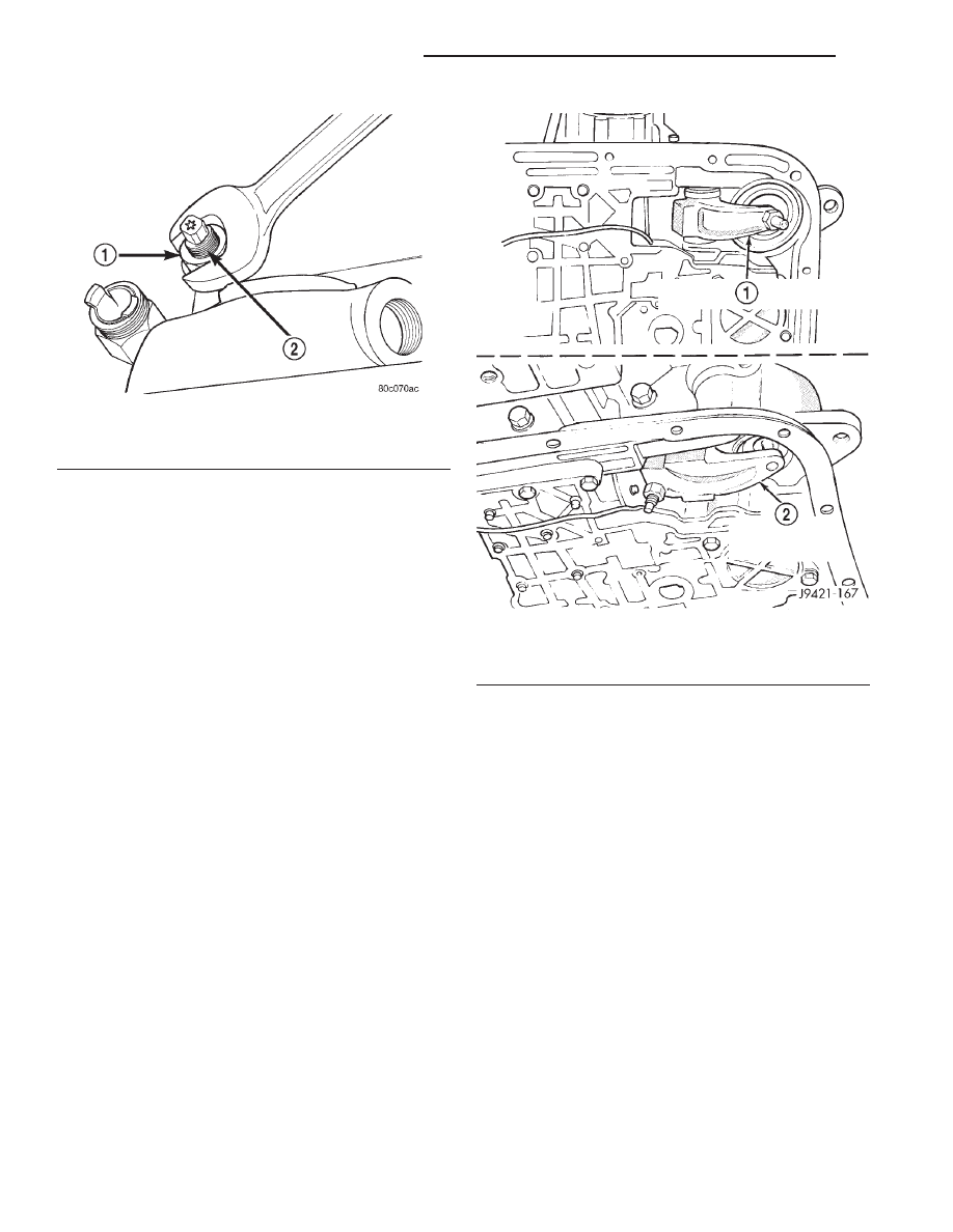
Fig. 232 Front Band Adjustment Screw Location
1 – LOCK-NUT
2 – FRONT BAND ADJUSTER
Fig. 233 Rear Band Adjustment Screw Location
1 – 30RH REAR BAND LEVER AND ADJUSTING SCREW
2 – 32RH REAR BAND LEVER AND ADJUSTING SCREW
21 - 200
AUTOMATIC TRANSMISSION—30RH
XJ
ADJUSTMENTS (Continued)