Jeep XJ. Manual - part 339


  Index      Jeep     Jeep XJ - service repair manual 2001 year


Search            


Content   ..  337  338  339  340   ..


Jeep XJ. Manual - part 339


(5) Disconnect electrical connectors at all 6 fuel

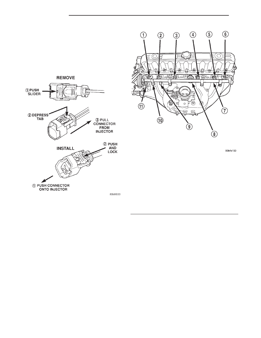
injectors. To remove connector refer to (Fig. 30). Push
red colored slider away from injector (1). While push-
ing slider, depress tab (2) and remove connector (3)
from injector. The factory fuel injection wiring har-
ness is numerically tagged (INJ 1, INJ 2, etc.) for
injector position identification. If harness is not
tagged, note wiring location before removal.

(6) Disconnect fuel supply line latch clip and fuel

line at fuel rail. Refer to Quick-Connect Fittings.

(7) Disconnect throttle cable at throttle body. Refer

to Throttle Cable Removal/Installation.

(8) Disconnect speed control cable at throttle body

(if equipped). Refer to Speed Control Cable in Group
8H, Speed Control System.

(9) Disconnect automatic transmission cable at

throttle body (if equipped).

(10) Remove cable routing bracket at intake man-

ifold.

(11) If equipped, remove wiring harnesses at injec-

tion rail studs by removing nuts.

(12) Clean dirt/debris from each fuel injector at

intake manifold.

(13) Remove fuel rail mounting nuts/bolts (Fig.

31).

(14) Remove fuel rail by gently rocking until all

the fuel injectors are out of intake manifold.

INSTALLATION

(1) Clean each injector bore at intake manifold.
(2) Apply a small amount of clean engine oil to

each injector o-ring. This will aid in installation.

(3) Position tips of all fuel injectors into the corre-

sponding injector bore in intake manifold. Seat injec-
tors into manifold.

(4) Install and tighten fuel rail mounting bolts to

11

63 N·m (100 625 in. lbs.) torque.

(5) If equipped, connect wiring harnesses to injec-

tion rail studs.

(6) Connect electrical connectors at all fuel injec-

tors. To install connector, refer to (Fig. 30). Push con-
nector onto injector (1) and then push and lock red
colored slider (2). Verify connector is locked to injec-
tor by lightly tugging on connector.

(7) Connect fuel line and fuel line latch clip to fuel

rail. Refer Quick-Connect Fittings..

Fig. 30 Remove/Install Fuel Injector Connector—

2.5L/4.0L Engine

Fig. 31 Fuel Rail Mounting—4.0L Engine

1 – INJ. #1
2 – INJ. #2
3 – INJ. #3
4 – INJ. #4
5 – INJ. #5
6 – INJ. #6
7 – FUEL INJECTOR RAIL
8 – FUEL DAMPER
9 – PRESSURE TEST PORT CAP
10 – MOUNTING BOLTS (4)
11 – QUICK-CONNECT FITTING

14 - 18

FUEL SYSTEM

XJ

REMOVAL AND INSTALLATION (Continued)

(8) Install protective cap to pressure test port fit-

ting (if equipped).

(9) Install cable routing bracket to intake mani-

fold.

(10) Connect throttle cable at throttle body.
(11) Connect speed control cable at throttle body (if

equipped).

(12) Connect

automatic

transmission

cable

at

throttle body (if equipped).

(13) Install air tube (or duct) at top of throttle

body.

(14) Install fuel tank cap.
(15) Connect negative battery cable to battery.
(16) Start engine and check for fuel leaks.

FUEL INJECTORS

REMOVAL

(1) Remove fuel rail. Refer to Fuel Injector Rail

Removal in this section.

(2) Disconnect clip(s) that retain fuel injector(s) to

fuel rail (Fig. 32).

INSTALLATION

(1) Install fuel injector(s) into fuel rail assembly

and install retaining clip(s).

(2) If same injector(s) is being reinstalled, install

new o-ring(s).

(3) Apply a small amount of clean engine oil to

each injector o-ring. This will aid in installation.

(4) Install fuel rail. Refer to Fuel Rail Installation.
(5) Start engine and check for fuel leaks.

FUEL TANK

WARNING: THE FUEL SYSTEM IS UNDER CON-
STANT FUEL PRESSURE EVEN WITH THE ENGINE
OFF.

THIS

PRESSURE

MUST

BE

RELEASED

BEFORE SERVICING FUEL TANK.

Two different procedures may be used to drain fuel

tank (lowering tank or using DRB scan tool).

The quickest draining procedure involves lowering

the fuel tank.

As an alternative procedure, the electric fuel pump

may be activated allowing tank to be drained at fuel
rail connection. Refer to DRB scan tool for fuel pump
activation procedures. Before disconnecting fuel line
at fuel rail, release fuel pressure. Refer to the Fuel
System Pressure Release Procedure in this group for
procedures. Attach end of special test hose tool num-
ber 6541, 6539, 6631 or 6923 at fuel rail disconnec-
tion (tool number will depend on model and/or engine
application). Position opposite end of this hose tool to
an approved gasoline draining station. Activate fuel
pump and drain tank until empty.

If electric fuel pump is not operating, tank must be

lowered for fuel draining. Refer to following proce-
dures.

REMOVAL

(1) Disconnect negative battery cable at battery.
(2) Release fuel system pressure. Refer to the Fuel

System Pressure Release Procedure in this group.

(3) Raise and support vehicle.
(4) If Equipped: Remove fuel tank skid plate. Refer

to Group 23, Body for procedures.

(5) Remove 4 fuel hose shield mounting bolts and

remove fuel hose shield (Fig. 33) from body.

(6) Remove fuel tank fill hose and vent hose

clamps at fuel tank filler tube (Fig. 34). Remove both
hoses at fuel filler tube (Fig. 34).

(7) Remove exhaust tailpipe heat shield mounting

bolts and remove shield.

CAUTION: To protect fuel tank from exhaust heat,
this shield must reinstalled after tank installation.

(8) Place a hydraulic jack to bottom of fuel tank.

WARNING: PLACE A SHOP TOWEL AROUND FUEL
LINES TO CATCH ANY EXCESS FUEL.

(9) Disconnect fuel supply line from fuel extension

line near front of fuel tank (Fig. 35). Refer to Fuel
Tubes/Lines/Hoses and Clamps in this group. Also
refer to Quick-Connect Fittings for procedures.

(10) Disconnect EVAP canister vent line near front

of tank (Fig. 35).

Fig. 32 Fuel Injector Mounting

1 – INLET FITTING
2 – FUEL INJECTOR RAIL
3 – CLIP
4 – FUEL INJECTOR

XJ

FUEL SYSTEM

14 - 19

REMOVAL AND INSTALLATION (Continued)

(11) Disconnect fuel pump module electrical con-

nector (pigtail harness) near front of tank (Fig. 35).
Harness connector is clipped to body.

(12) Remove two fuel tank strap nuts (Fig. 36).

Position both tank support straps away from tank.

(13) Carefully lower right side of tank while feed-

ing both fuel hoses through access hole in body. Fuel
Tank Full And Not Drained Using DRB Scan
Tool: 
To prevent fuel loss through hoses, keep left
side of tank higher than right side while lowering.

Do not allow hose openings to drop lower than top of
tank.

(14) Continue lowering tank until clear of vehicle.

Place tank on floor with left side (hose side) higher
than right side.

(15) Drain tank by removing fuel fill hose at tank.

Fuel fill hose is largest of 2 hoses (Fig. 37). Insert the

Fig. 33 Fuel Hose Shield

1 – FUEL HOSE SHIELD
2 – MOUNTING BOLTS (4)

Fig. 34 Fuel Fill and Vent Hoses

1 – CLAMPS
2 – FUEL FILL HOSE
3 – FUEL VENT HOSE

Fig. 35 Fuel Tank Connections at Front of Fuel Tank

1 – FUEL PUMP MODULE CONNECTOR
2 – LEFT-REAR SHOCK ABSORBER
3 – EVAP CANISTER VENT LINE CONNECTION
4 – FRONT OF FUEL TANK
5 – FUEL SUPPLY LINE CONNECTION

Fig. 36 Fuel Tank Mounting Straps/Nuts

1 – FRONT OF FUEL TANK
2 – NUTS (2)
3 – STRAPS (2)

14 - 20

FUEL SYSTEM

XJ

REMOVAL AND INSTALLATION (Continued)

drain hose (from an approved gasoline draining sta-
tion) into hose opening. Drain tank until empty.

(16) If fuel pump module removal is necessary,

refer to Fuel Pump Module Removal/Installation in
this group for procedures.

INSTALLATION

(1) If fuel pump module is being installed, refer to

Fuel Pump Module Removal/Installation in this
group for procedures.

(2) Install fuel fill/vent hoses to tank fittings. To

prevent hose from kinking, rotate each hose until
index mark on hose is aligned to index tang on fuel
tank (Fig. 37).

(3) Install hose clamps to hoses. Position clamps

between index marks on each hose (Fig. 37).

(4) Position fuel tank to hydraulic jack.
(5) Raise tank into position while guiding fuel fill

and vent hoses into and through access hole in body.

(6) Continue raising tank until positioned to body.
(7) Attach two fuel tank mounting straps and

mounting nuts. Tighten nuts to 10 N·m (90 in. lbs.)
torque. Do not over tighten nuts.

(8) Install both fuel hoses to fuel fill tube. Tighten

both retaining clamps.

(9) Position fuel hose shield to body. Install and

tighten 4 mounting bolts.

(10) Connect fuel pump module pigtail harness

electrical connector near front of tank.

(11) Connect fuel pump module supply line near

front of tank. Refer to Quick-Connect Fittings for
procedures.

(12) Connect EVAP hose near front of tank.
(13) Install exhaust tailpipe heat shield.
(14) Install fuel tank skid plate (if equipped).
(15) Lower vehicle and connect battery cable to

battery.

FUEL TANK FILLER TUBE CAP

REMOVAL/INSTALLATION

If replacement of the 1/4 turn fuel tank filler tube

cap is necessary, it must be replaced with an identi-
cal cap to be sure of correct system operation.

CAUTION: Remove the fuel tank filler tube cap to
relieve

fuel

tank

pressure.

The

cap

must

be

removed prior to disconnecting any fuel system
component or before draining the fuel tank.

ACCELERATOR PEDAL

REMOVAL

The accelerator pedal is connected to the throttle

body linkage by the throttle cable. The cable is pro-
tected by a plastic sheathing and is connected to the
throttle body linkage by a ball socket. It is connected
to the upper part of the accelerator pedal arm by a
plastic retainer (clip) (Fig. 38). This retainer (clip)
snaps into the top of the accelerator pedal arm.
Retainer tabs (built into the cable sheathing) (Fig.
38) fasten the cable to the dash panel.

Dual throttle return springs (attached to the throt-

tle shaft) are used to close the throttle.

CAUTION: Never attempt to remove or alter these
springs.

CAUTION: Be careful not to damage or kink the
cable core wire (within the cable sheathing) while
servicing the accelerator pedal or throttle cable.

(1) From inside the vehicle, hold up accelerator

pedal. Remove plastic cable retainer (clip) and throt-
tle cable core wire from upper end of accelerator
pedal arm (Fig. 38). Plastic cable retainer (clip) snaps
into pedal arm.

(2) Remove accelerator pedal mounting bracket

nuts. Remove accelerator pedal assembly.

Fig. 37 Fuel Fill/Vent Hose Index Marks

1 – FUEL TANK
2 – CLAMP INDEX MARKS
3 – TANK INDEX TANGS
4 – HOSE INDEX MARKS
5 – FUEL FILL HOSE
6 – CLAMP INDEX MARKS
7 – CLAMPS
8 – FUEL VENT HOSE

XJ

FUEL SYSTEM

14 - 21

REMOVAL AND INSTALLATION (Continued)


Content   ..  337  338  339  340   ..