Jeep XJ. Manual - part 286
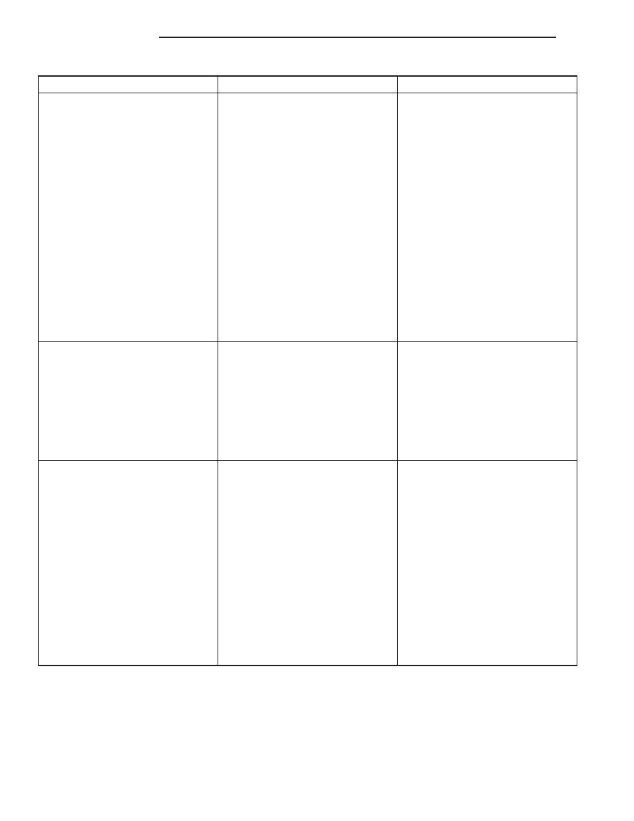
CONDITION
POSSIBLE CAUSES
CORRECTION
LOW OIL PRESSURE
1. Low oil level
1. Check oil level and fill if
necessary
2. Faulty oil pressure sending unit
2. Install new sending unit
3. Clogged oil filter
3. Install new oil filter
4. Worn oil pump
4. Replace worn gears or oil pump
assy
5. Thin or diluted oil
5. Change oil to correct viscosity.
Refer to this group for correct
procedure/engine oil specifications
6. Excessive bearing clearance
6. Measure bearings for correct
clearance
7. Oil pump relief valve stuck
7. Remove valve to inspect, clean
and reinstall
8. Oil pump suction tube loose,
broken, bent or clogged
8. Inspect suction tube and clean or
replace if necessary
9. Oil pump cover warped or
cracked
9. Install new oil pump
OIL LEAKS
1. Misaligned or deteriorated
gaskets
1. Replace gasket
2. Loose fastener, broken or porous
metal part
2. Tighten, repair or replace the part
3. Front or rear crankshaft oil seal
leaking
3. Replace seal
4. Leaking oil gallery plug or cup
plug
4. Remove and reseal threaded
plug. Replace cup style plug
EXCESSIVE OIL CONSUMPTION
OR SPARK PLUGS OIL FOULED
1. PCV System malfunction
1. Refer to group 25, Emission
Control System for correct operation
2. Defective valve stem seal(s)
2. Repair or replace seal(s)
3. Worn or broken piston rings
3. Hone cylinder bores. Install new
rings
4. Scuffed pistons/cylinder walls
4. Hone cylinder bores and replace
pistons as required
5. Carbon in oil control ring groove
5. Remove rings and de-carbon
piston
6. Worn valve guides
6. Inspect/replace valve guides as
necessary
7. Piston rings fitted too tightly in
grooves
7. Remove rings and check ring end
gap and side clearance. Replace if
necessary
9 - 12
2.5L ENGINE
XJ
DIAGNOSIS AND TESTING (Continued)