Jeep XJ. Manual - part 143


  Index      Jeep     Jeep XJ - service repair manual 2001 year


Search            


Content   ..  141  142  143  144   ..


Jeep XJ. Manual - part 143


LIFTGATE

(1) Disconnect and isolate the battery negative

cable.

(2) Open the liftgate.
(3) Remove the liftgate trim panel from the lift-

gate. Refer to Group 23 - Body for the procedures.

(4) Reach through the liftgate inner panel access

hole and disconnect the link from the clip on the
power lock motor (Fig. 5).

(5) Remove the two screws that secure the power

lock motor to the liftgate inner panel.

(6) Pull the power lock motor out through the lift-

gate inner panel access hole far enough to access the
wire harness connector.

(7) Unplug the wire harness connector from the

power lock motor.

(8) Remove the power lock motor from the liftgate.
(9) Reverse the removal procedures to install.

Tighten the power lock motor mounting screws to 3
N·m (28 in. lbs.).

REMOTE KEYLESS ENTRY RECEIVER

CAUTION: A discharge of static electricity may
damage this unit. At no time should any source of
static electricity be permitted near this unit. Techni-
cians handling or servicing the unit should wear

cotton clothing, not synthetic fabric clothing; and,
should ground themselves before and during all
handling and service procedures. Electrically con-
ductive wrist or heel straps are recommended, or
static dissipating shoes are also acceptable. Work
and storage areas should be free of static genera-
tive materials such as: dry air, glass, nylon, wool,
fur, silk, rayon, acrylic, polystyrene foam, polyester,
saran,

polyethylene,

polypropylene,

PVC,

and

teflon.

MINI-DOME MOUNTED TYPE

(1) Disconnect and isolate the battery negative

cable.

(2) Remove the two screws that secure the Remote

Keyless Entry (RKE) mini-dome housing to the roof
panel reinforcement (Fig. 6).

(3) Lower the front of the mini-dome housing and

slide the unit forward to disengage the rear mount-
ing tab from the headliner.

(4) Lower the mini-dome housing far enough to

access the RKE receiver wire harness connector.

(5) Unplug the wire harness connector from the

RKE receiver.

(6) Remove the RKE mini-dome unit from the

headliner.

(7) Reverse the removal procedures to install.

Tighten the mounting screws to 2.8 N·m (24 in. lbs.).

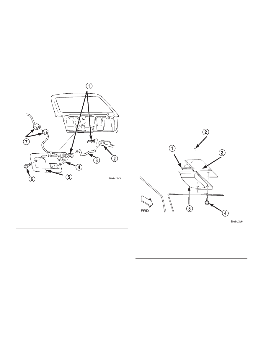
Fig. 5 Liftgate Power Lock Motor Remove/Install

1 – CLIPS
2 – LOCK LEVER
3 – LINK
4 – MOTOR
5 – LIFTGATE INNER PANEL
6 – SCREW
7 – CONNECTORS

Fig. 6 Mini-Dome Housing Remove/Install

1 – MOUNTING TAB
2 – HEADLINER
3 – REINFORCEMENT
4 – SCREW
5 – MINI-DOME HOUSING

8P - 8

POWER LOCK SYSTEMS

XJ

REMOVAL AND INSTALLATION (Continued)

OVERHEAD CONSOLE MOUNTED TYPE

(1) Disconnect and isolate the battery negative

cable.

(2) Remove the overhead console from the head-

liner. Refer to Overhead Console in Group 8V - Over-
head Console Systems for the procedures.

(3) Remove the six screws that secure the rear

overhead console housing to the overhead console
bezel (Fig. 7).

(4) Gently flex the sides of the overhead console

bezel far enough to clear the tabs on the rear console
housing and remove the housing from the bezel.

(5) Remove the two screws that secure the RKE

receiver circuit board to the rear overhead console
housing.

(6) Remove the RKE circuit board from the rear

overhead console housing.

(7) Reverse the removal procedures to install.

Tighten the mounting screws to 2.2 N·m (20 in. lbs.).

Fig. 7 RKE Receiver Remove/Install

1 – REAR OVERHEAD CONSOLE HOUSING
2 – RKE RECEIVER
3 – TABS
4 – OVERHEAD CONSOLE BEZEL
5 – SCREWS

XJ

POWER LOCK SYSTEMS

8P - 9

REMOVAL AND INSTALLATION (Continued)

VEHICLE THEFT/SECURITY SYSTEMS

TABLE OF CONTENTS

page

page

GENERAL INFORMATION

INTRODUCTION . . . . . . . . . . . . . . . . . . . . . . . . . . 1
SENTRY KEY IMMOBILIZER SYSTEM . . . . . . . . . 1

DESCRIPTION AND OPERATION

SENTRY KEY IMMOBILIZER MODULE. . . . . . . . . 1
SENTRY KEY IMMOBILIZER TRANSPONDER . . . 2
SENTRY KEY IMMOBILIZER SYSTEM

INDICATOR LAMP . . . . . . . . . . . . . . . . . . . . . . . 3

DIAGNOSIS AND TESTING

SENTRY KEY IMMOBILIZER SYSTEM . . . . . . . . . 3

SERVICE PROCEDURES

SENTRY KEY IMMOBILIZER SYSTEM

TRANSPONDER PROGRAMMING . . . . . . . . . . . 4

REMOVAL AND INSTALLATION

SENTRY KEY IMMOBILIZER MODULE. . . . . . . . . 4

GENERAL INFORMATION

INTRODUCTION

The Sentry Key Immobilizer System (SKIS) is

available factory-installed optional equipment for this
model. Following are some general descriptions of the
features and components of the SKIS. Refer to the
vehicle owner’s manual for more information on the
use and operation of the SKIS. Refer to 8W-30 - Fuel/
Ignition System in Group 8W - Wiring Diagrams for
complete circuit descriptions and diagrams.

SENTRY KEY IMMOBILIZER SYSTEM

The Sentry Key Immobilizer System (SKIS) is

designed to provide passive protection against unau-
thorized vehicle use by preventing the engine from
operating while the system is armed. The primary
components of this system are the Sentry Key Immo-
bilizer Module (SKIM), the Sentry Key transponder,
the SKIS indicator lamp, and the Powertrain Control
Module (PCM).

The SKIM is installed on the steering column near

the ignition lock cylinder. The transponder is located
under the molded rubber cap on the head of the igni-
tion key. The SKIS indicator lamp is located in the
instrument cluster.

The SKIS includes two valid Sentry Key transponders

from the factory. If the customer wishes, additional non-
coded blank Sentry Keys are available. These blank
keys can be cut to match a valid ignition key, but the
engine will not start unless the key transponder is also
programmed to the vehicle using the Customer Learn
programming procedure or a DRBIII

t scan tool. The

SKIS will recognize no more than eight valid Sentry
Key transponders at any one time.

The SKIS performs a self-test each time the igni-

tion switch is turned to the On position, and will
store Diagnostic Trouble Codes (DTCs) if a system

malfunction is detected. The SKIS can be diagnosed,
and any stored DTC can be retrieved using a
DRBIII

t scan tool as described in the proper Diag-

nostic Procedures manual.

DESCRIPTION AND OPERATION

SENTRY KEY IMMOBILIZER MODULE

The Sentry Key Immobilizer Module (SKIM) con-

tains a Radio Frequency (RF) transceiver and a cen-
tral processing unit, which includes the Sentry Key
Immobilizer System (SKIS) program logic. The SKIS
programming enables the SKIM to program and
retain in memory the codes of at least one, but no
more than eight electronically coded Sentry Key
transponders. The SKIS programming also enables
the SKIM to communicate over the Chrysler Collision
Detection (CCD) data bus network with the Power-
train Control Module (PCM), the instrument cluster
and/or the DRBIII

t scan tool.

The SKIM transmits and receives RF signals

through a tuned antenna enclosed within a molded
plastic ring formation that is integral to the SKIM
housing. When the SKIM is properly installed on the
steering column, the antenna ring is oriented around
the circumference of the ignition lock cylinder hous-
ing. This antenna ring must be located within eight
millimeters (0.31 inches) of the Sentry Key in order
to ensure proper RF communication between the
SKIM and the Sentry Key transponder.

For added system security, each SKIM is pro-

grammed with a unique “Secret Key” code and a
security code (PIN). The SKIM keeps the “Secret
Key” code in memory. This “Secret Key” code must be
transferred to the PCM memory during the initializa-
tion/programming of the SKIS when the vehicle is
manufactured, and each time the PCM is replaced
during vehicle service by the dealer technician. The

XJ

VEHICLE THEFT/SECURITY SYSTEMS

8Q - 1


Content   ..  141  142  143  144   ..