Jeep XJ. Manual - part 103
CIGAR LIGHTER RELAY
WARNING: ON VEHICLES EQUIPPED WITH AIR-
BAGS,
REFER
TO
GROUP
8M
-
PASSIVE
RESTRAINT SYSTEMS BEFORE ATTEMPTING ANY
STEERING
WHEEL,
STEERING
COLUMN,
OR
INSTRUMENT PANEL COMPONENT DIAGNOSIS OR
SERVICE. FAILURE TO TAKE THE PROPER PRE-
CAUTIONS COULD RESULT IN ACCIDENTAL AIR-
BAG DEPLOYMENT AND POSSIBLE PERSONAL
INJURY.
REMOVAL
(1) Disconnect and isolate the battery negative
cable.
(2) Remove the fuse access panel by unsnapping it
from the right cowl side trim panel.
(3) Remove the stamped nut that secures the right
cowl side trim to the junction block stud (Fig. 9).
(4) Remove the screw located above the fuse access
opening that secures the right cowl side trim to the
right cowl side inner panel.
(5) Remove the screw that secures the right door
sill trim and the right cowl side trim to the right
door opening sill.
(6) Remove the right cowl side trim panel from the
vehicle.
(7) Refer to Junction Block in the Contents of
Group 8W - Wiring Diagrams for cigar lighter relay
identification and location.
(8) Remove the cigar lighter relay from the recep-
tacle in the junction block.
INSTALLATION
(1) Refer to Junction Block in the Contents of
Group 8W - Wiring Diagrams for the proper cigar
lighter relay location.
(2) Position the cigar lighter relay to the receptacle
in the junction block.
(3) Align the terminals of the cigar lighter relay
with the cavities in the junction block receptacle.
(4) Push on the cigar lighter relay case firmly and
evenly until all of the relay terminals are fully seated
within the cavities of the junction block receptacle.
(5) Position the right cowl side trim to the right
door sill trim.
(6) Install and tighten the screw that secures the
right cowl side trim to the right door sill trim.
Tighten the screw to 2.2 N·m (20 in. lbs.).
(7) Position the right cowl side trim to the right
cowl side inner panel.
(8) Install and tighten the screw that secures the
right cowl side trim to the right cowl side inner
panel. Tighten the screw to 2.2 N·m (20 in. lbs.).
(9) Install the stamped nut that secures the right
cowl side trim to the junction block stud.
(10) Install the fuse access panel by snapping it
onto the right cowl side trim panel.
(11) Reconnect the battery negative cable.
CLUSTER BEZEL
WARNING: ON VEHICLES EQUIPPED WITH AIR-
BAGS,
REFER
TO
GROUP
8M
-
PASSIVE
RESTRAINT SYSTEMS BEFORE ATTEMPTING ANY
STEERING
WHEEL,
STEERING
COLUMN,
OR
INSTRUMENT PANEL COMPONENT DIAGNOSIS OR
SERVICE. FAILURE TO TAKE THE PROPER PRE-
CAUTIONS COULD RESULT IN ACCIDENTAL AIR-
BAG DEPLOYMENT AND POSSIBLE PERSONAL
INJURY.
REMOVAL
(1) Disconnect and isolate the battery negative
cable.
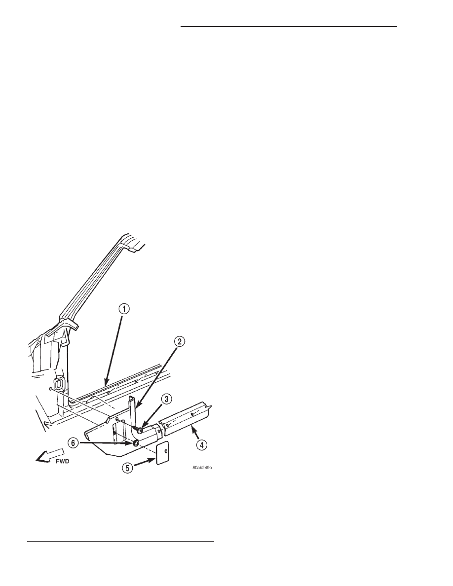
Fig. 9 Right Cowl Side Trim Remove/Install
1 – RIGHT FRONT DOOR SILL
2 – COWL SIDE TRIM PANEL
3 – SCREW
4 – SILL TRIM
5 – FUSE ACCESS PANEL
6 – PUSH-NUT
8E - 16
INSTRUMENT PANEL SYSTEMS
XJ
REMOVAL AND INSTALLATION (Continued)