Jeep XJ. Manual - part 53


  Index      Jeep     Jeep XJ - service repair manual 2001 year


Search            


Content   ..  51  52  53  54   ..


Jeep XJ. Manual - part 53


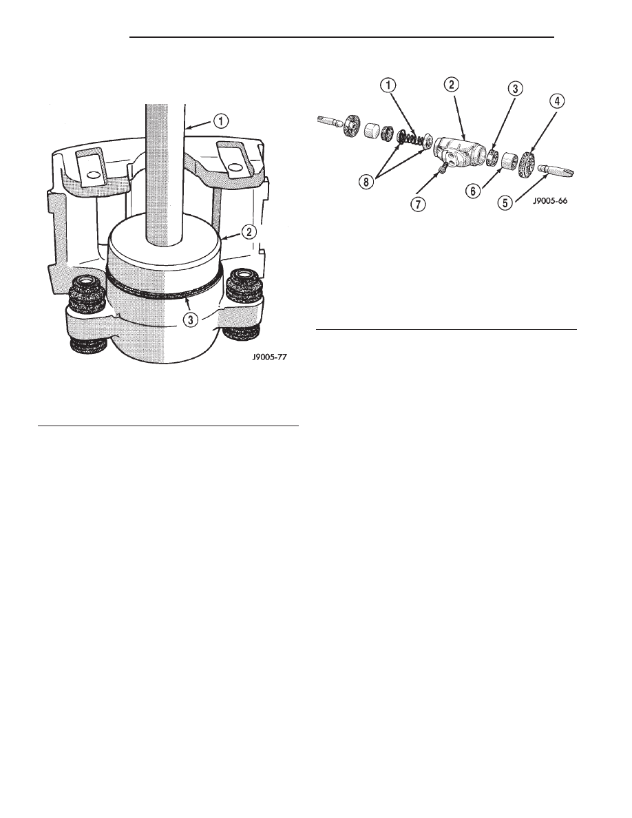
(8) Seat dust boot in caliper with Installer Tool

C-4842 and Tool Handle C-4171 (Fig. 54).

(9) Replace caliper bleed screw if removed.

WHEEL CYLINDER

DISASSEMBLY

(1) Remove push rods and boots (Fig. 55).
(2) Press pistons, cups and spring and expander

out of cylinder bore.

(3) Remove bleed screw.

ASSEMBLY

(1) Lubricate wheel cylinder bore, pistons, piston

cups and spring and expander with clean brake fluid.

(2) Install first piston in cylinder bore. Then

install first cup in bore and against piston. Be sure
lip of piston cup is facing inward (toward
spring and expander) and flat side is against
piston.

(3) Install

spring

and

expander

followed

by

remaining piston cup and piston.

(4) Install boots on each end of cylinder and insert

push rods in boots.

(5) Install cylinder bleed screw.

CLEANING AND INSPECTION

CALIPER

CLEANING

Clean the caliper components with clean brake

fluid or brake clean only. Wipe the caliper and piston
dry with lint free towels or use low pressure com-
pressed air.

CAUTION: Do not use gasoline, kerosene, thinner,
or similar solvents. These products may leave a
residue that could damage the piston and seal.

INSPECTION

The piston is made from a phenolic resin (plastic

material) and should be smooth and clean.

The piston must be replaced if cracked or scored.

Do not attempt to restore a scored piston surface by
sanding or polishing.

CAUTION: If the caliper piston is replaced, install
the same type of piston in the caliper. Never inter-
change phenolic resin and steel caliper pistons.
The pistons, seals, seal grooves, caliper bore and
piston tolerances are different.

The bore can be lightly polished with a brake

hone to remove very minor surface imperfections
(Fig. 56). The caliper should be replaced if the bore is
severely corroded, rusted, scored, or if polishing
would increase bore diameter more than 0.025 mm
(0.001 inch).

Fig. 54 Piston Dust Boot Installation

1 – HANDLE C-4171
2 – INSTALLER C-4842
3 – DUST BOOT

Fig. 55 Wheel Cylinder Components–Typical

1 – SPRING
2 – CYLINDER
3 – PISTON CLIP
4 – BOOT
5 – PUSH ROD
6 – PISTON
7 – BLEED SCREW
8 – CUP EXPANDERS

5 - 28

BRAKES

XJ

DISASSEMBLY AND ASSEMBLY (Continued)

REAR DRUM BRAKE

CLEANING

Clean the individual brake components, including

the support plate and wheel cylinder exterior, with a
water dampened cloth or with brake cleaner. Do not
use any other cleaning agents. Remove light rust and
scale from the brake shoe contact pads on the sup-
port plate with fine sandpaper.

INSPECTION

As a general rule, riveted brake shoes should be

replaced when worn to within 0.78 mm (1/32 in.) of
the rivet heads. Bonded lining should be replaced
when worn to a thickness of 1.6 mm (1/16 in.).

Examine the lining contact pattern to determine if

the shoes are bent or the drum is tapered. The lining
should exhibit contact across its entire width. Shoes
exhibiting contact only on one side should be
replaced and the drum checked for runout or taper.

Inspect the adjuster screw assembly. Replace the

assembly if the star wheel or threads are damaged,
or the components are severely rusted or corroded.

Discard the brake springs and retainer components

if worn, distorted or collapsed. Also replace the
springs if a brake drag condition had occurred. Over-
heating will distort and weaken the springs.

Inspect the brake shoe contact pads on the support

plate, replace the support plate if any of the pads are
worn or rusted through. Also replace the plate if it is
bent or distorted (Fig. 57).

WHEEL CYLINDER

CLEANING

Clean the cylinder and pistons with clean brake

fluid or brake cleaner only. Do not use any other
cleaning agents.

Dry the cylinder and pistons with compressed air.

Do not use rags or shop towels to dry the cylinder
components. Lint from cloth material will adhere to
the cylinder bores and pistons.

INSPECTION

Inspect the cylinder bore. Light discoloration and

dark stains in the bore are normal and will not
impair cylinder operation.

The cylinder bore can be lightly polished but only

with crocus cloth. Replace the cylinder if the bore is
scored, pitted or heavily corroded. Honing the bore to
restore the surface is not recommended.

Inspect the cylinder pistons. The piston surfaces

should be smooth and free of scratches, scoring and
corrosion. Replace the pistons if worn, scored, or cor-
roded. Do attempt to restore the surface by sanding
or polishing.

Discard the old piston cups and the spring and

expander. These parts are not reusable. The original
dust boots may be reused but only if they are in good
condition.

Fig. 56 Polishing Piston Bore

1 – SPECIAL HONE
2 – CALIPER
3 – PISTON BORE

Fig. 57 Shoe Contact Surfaces

1 – ANCHOR PIN
2 – SUPPORT PLATE
3 – SHOE CONTACT SURFACES

XJ

BRAKES

5 - 29

CLEANING AND INSPECTION (Continued)

ADJUSTMENTS

BRAKE LAMP SWITCH

(1) Press and hold brake pedal in applied position.
(2) Pull switch plunger all the way out to fully

extended position.

(3) Release brake pedal. Then pull pedal lightly

rearward. Pedal will set plunger to correct position
as pedal pushes plunger into switch body. Switch will
make ratcheting sound as it self adjusts.

CAUTION: Booster damage may occur if the pedal
pull exceeds 20 lbs..

REAR DRUM BRAKE

The rear drum brakes are equipped with a self-ad-

justing mechanism. Under normal circumstances, the
only time adjustment is required is when the shoes
are replaced, removed for access to other parts, or
when one or both drums are replaced.

Adjustment can be made with a standard brake

gauge or with adjusting tool. Adjustment is per-
formed with the complete brake assembly installed
on the backing plate.

ADJUSTMENT WITH BRAKE GAUGE

(1) Be sure parking brakes are fully released.
(2) Raise rear of vehicle and remove wheels and

brake drums.

(3) Verify that left and right automatic adjuster

levers and cables are properly connected.

(4) Insert brake gauge in drum. Expand gauge

until gauge inner legs contact drum braking surface.
Then lock gauge in position (Fig. 58).

(5) Reverse gauge and install it on brake shoes.

Position gauge legs at shoe centers as shown (Fig.
59). If gauge does not fit (too loose/too tight), adjust
shoes.

(6) Pull shoe adjuster lever away from adjuster

screw star wheel.

(7) Turn adjuster screw star wheel (by hand) to

expand or retract brake shoes. Continue adjustment
until gauge outside legs are light drag-fit on shoes.

(8) Install brake drums and wheels and lower

vehicle.

(9) Drive vehicle and make one forward stop fol-

lowed by one reverse stop. Repeat procedure 8-10
times to operate automatic adjusters and equalize
adjustment.

NOTE: Bring vehicle to complete standstill at each
stop. Incomplete, rolling stops will not activate
automatic adjusters.

ADJUSTMENT WITH ADJUSTING TOOL

(1) Be sure parking brake lever is fully released.
(2) Raise vehicle so rear wheels can be rotated

freely.

(3) Remove plug from each access hole in brake

support plates.

(4) Loosen parking brake cable adjustment nut

until there is slack in front cable.

(5) Insert adjusting tool through support plate

access hole and engage tool in teeth of adjusting
screw star wheel (Fig. 60).

(6) Rotate adjuster screw star wheel (move tool

handle upward) until slight drag can be felt when
wheel is rotated.

Fig. 58 Adjusting Gauge On Drum

1 – BRAKE GAUGE
2 – BRAKE DRUM

Fig. 59 Adjusting Gauge On Brake Shoes

1 – BRAKE GAUGE
2 – BRAKE SHOES

5 - 30

BRAKES

XJ

2000 JEEP CHEROKEE

(7) Push and hold adjuster lever away from star

wheel with thin screwdriver.

(8) Back off adjuster screw star wheel until brake

drag is eliminated.

(9) Repeat adjustment at opposite wheel. Be sure

adjustment is equal at both wheels.

(10) Install support plate access hole plugs.
(11) Adjust parking brake cable and lower vehicle.
(12) Drive vehicle and make one forward stop fol-

lowed by one reverse stop. Repeat procedure 8-10
times to operate automatic adjusters and equalize
adjustment.

NOTE: Bring vehicle to complete standstill at each
stop. Incomplete, rolling stops will not activate
automatic adjusters.

PARKING BRAKE CABLE TENSIONER

NOTE: Parking brake adjustment is only necessary
when the tensioner, or a cable has been replaced or
disconnected.

ADJUSTMENT

(1) Raise vehicle.
(2) Back off tensioner adjusting nut to create slack

in cables.

(3) Remove rear wheel/tire assemblies and remove

brake drums.

(4) Check rear brake shoe adjustment with stan-

dard brake gauge.

CAUTION: Excessive shoe-to-drum clearance, or
worn brake components will result in faulty parking
brake adjustment and operation.

(5) Verify that parking brake cables operate freely

and are not binding, or seized. Replace faulty cables,
before proceeding.

(6) Reinstall brake drums and wheel/tire assem-

blies after brake shoe adjustment is complete.

(7) Lower vehicle enough for access to parking

brake lever. Then fully apply parking brakes. Leave
brakes applied until adjustment is complete.

(8) Raise vehicle and mark tensioner rod 6.5 mm

(1/4 in.) from tensioner bracket (Fig. 61).

(9) Tighten adjusting nut at equalizer until mark

on tensioner rod moves into alignment with tensioner
bracket.

(10) Lower vehicle until rear wheels are 15-20 cm

(6-8 in.) off shop floor.

(11) Release parking brake lever and verify that

rear wheels rotate freely without drag.

(12) Lower vehicle.

NOTE: Do not loosen/tighten equalizer adjusting
nut for any reason after completing adjustment.

SPECIFICATIONS

BRAKE FLUID

The brake fluid used in this vehicle must conform

to DOT 3 specifications and SAE J1703 standards.
No other type of brake fluid is recommended or
approved for usage in the vehicle brake system. Use

Fig. 60 Brake Adjustment

1 – STAR WHEEL
2 – LEVER
3 – BRAKE SHOE WEB
4 – SCREWDRIVER
5 – ADJUSTING TOOL
6 – ADJUSTER SPRING

Fig. 61 Tensioner Rod Measurement

1 – TENSIONER BRACKET
2 – 6.5 mm (1/4 in.)
3 – TENSIONER ROD
4 – ROD TO EQUALIZER

XJ

BRAKES

5 - 31

ADJUSTMENTS (Continued)


Content   ..  51  52  53  54   ..