Jeep XJ. Manual - part 41


  Index      Jeep     Jeep XJ - service repair manual 2001 year


Search            


Content   ..  39  40  41  42   ..


Jeep XJ. Manual - part 41


(6) Position the pinion yoke on the end of the shaft

with the reference marks aligned.

(7) Seat yoke on pinion shaft with Installer C-3718

and Wrench 6719.

(8) Remove the tools and install the pinion yoke

washer. The convex side of the washer must face out-
ward.

CAUTION: Do not exceed the minimum tightening
torque when installing the pinion yoke retaining nut
at this point. Damage to collapsible spacer or bear-
ings may result.

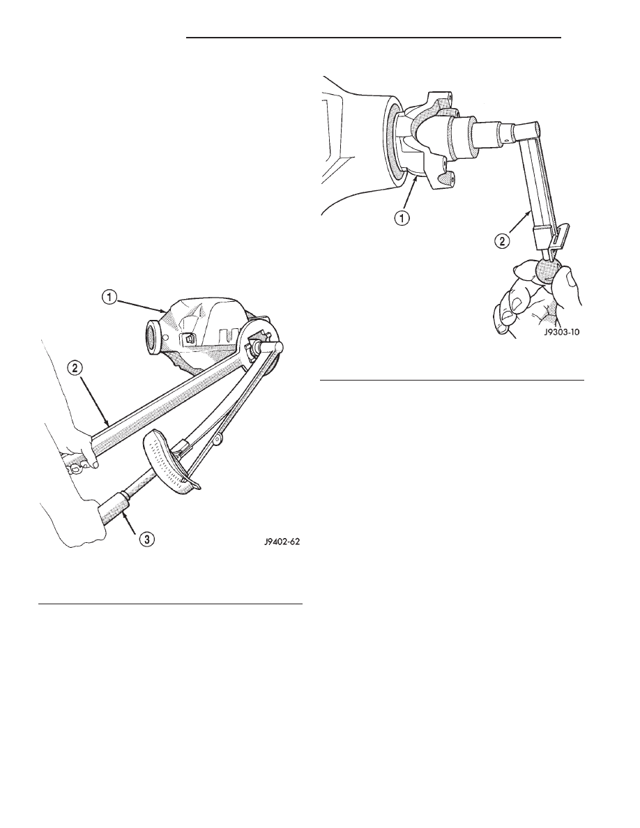
(9) Hold pinion yoke with Yoke Holder 6719 and

tighten shaft nut to 285 N·m (210 ft. lbs.) (Fig. 15).
Rotate the pinion several revolutions to ensure the
bearing rollers are seated.

(10) Rotate the pinion using an (in. lbs.) torque

wrench. Rotating torque should be equal to the read-
ing recorded during removal, plus an additional 0.56
N·m (5 in. lbs.) (Fig. 16).

CAUTION: Never loosen pinion nut to decrease pin-
ion gear bearing rotating torque and never exceed
specified

preload

torque.

If

preload

torque

is

exceeded

a

new

collapsible

spacer

must

be

installed. The torque sequence will then have to be
repeated.

(11) If the rotating torque is low, use Yoke Holder

6719 to hold the pinion yoke (Fig. 15) and tighten the
pinion nut in 6.8 N·m (5 ft. lbs.) increments until
proper rotating torque is achieved.

NOTE: The bearing rotating torque should be con-
stant during a complete revolution of the pinion. If
the rotating torque varies, this indicates a binding
condition.

(12) The seal replacement is unacceptable if the

final pinion nut torque is less than 285 N·m (210 ft.
lbs.).

(13) Install the propeller shaft with the installa-

tion reference marks aligned.

(14) Tighten the universal joint yoke clamp screws

to 19 N·m (14 ft. lbs.).

(15) Install the brake drums.
(16) Install wheel and tire assemblies and lower

the vehicle.

(17) Check the differential housing lubricant level.

DIFFERENTIAL

REMOVAL

(1) Remove the axle shafts.

NOTE: Side play resulting from bearing races being
loose on case hubs requires replacement of the dif-
ferential case.

Fig. 15 Tightening Pinion Nut

1 – DIFFERENTIAL HOUSING
2 – YOKE HOLDER
3 – TORQUE WRENCH

Fig. 16 Check Pinion Rotation Torque

1 – PINION YOKE
2 – INCH POUND TORQUE WRENCH

3 - 114

8 1/4 REAR AXLE

XJ

REMOVAL AND INSTALLATION (Continued)

(2) Mark the differential housing and the differen-

tial bearing caps for installation reference (Fig. 17).

(3) Remove bearing threaded adjuster lock from

each bearing cap. Loosen the bolts, but do not
remove the bearing caps.

(4) Loosen the threaded adjusters with Wrench

C-4164 (Fig. 18).

(5) Hold the differential case while removing bear-

ing caps and adjusters.

(6) Remove the differential case.

NOTE: Each differential bearing cup and threaded
adjuster must be kept with their respective bearing.

INSTALLATION

(1) Apply a coating of hypoid gear lubricant to the

differential bearings, bearing cups, and threaded
adjusters. A dab of grease can be used to keep the
adjusters in position. Carefully position the assem-
bled differential case in the housing.

(2) Observe the reference marks and install the

differential bearing caps at their original locations
(Fig. 19).

(3) Install bearing cap bolts and tighten the upper

bolts to 14 N·m (10 ft. lbs.). Tighten the lower bolts
finger-tight until the bolt head is seated.

(4) Perform the differential bearing preload and

adjustment procedure.

NOTE: Be sure that all bearing cap bolts are tight-
ened to the final torque of 95 N·m (70 ft.lbs) before
proceeding.

(5) Install axle shafts and differential housing

cover.

DIFFERENTIAL SIDE BEARINGS

REMOVAL

(1) Remove differential case from axle housing.
(2) Remove the bearings from the differential case

with Puller/Press C-293-PA and Adapters C-293-48
and Plug SP-3289 (Fig. 20).

INSTALLATION

(1) Install differential side bearings. Use Installer

C-4340 with handle C-4171 (Fig. 21).

(2) Install differential case in axle housing.

Fig. 17 Mark For Installation Reference

1 – INSTALLATION REFERENCE MARKS
2 – INSTALLATION REFERENCE MARKS
3 – DIFFERENTIAL HOUSING
4 – BEARING CAP

Fig. 18 Threaded Adjuster Tool

1 – AXLE TUBE
2 – BACKING PLATE
3 – TOOL C-4164

Fig. 19 Bearing Caps & Bolts

1 – INSTALLATION REFERENCE MARKS
2 – INSTALLATION REFERENCE MARKS
3 – DIFFERENTIAL HOUSING
4 – BEARING CAP

XJ

8 1/4 REAR AXLE

3 - 115

REMOVAL AND INSTALLATION (Continued)

RING GEAR

The ring gear and pinion are serviced in a matched

set. Do not replace the ring gear without replacing
the pinion.

REMOVAL

(1) Remove differential from axle housing.
(2) Place differential case in a suitable vise with

soft metal jaw protectors. (Fig. 22).

(3) Remove bolts holding ring gear to differential

case.

(4) Using a soft hammer, drive ring gear from dif-

ferential case (Fig. 22).

INSTALLATION

CAUTION: Do not reuse the bolts that held the ring
gear to the differential case. The bolts can fracture
causing extensive damage.

(1) Invert the differential case.

(2) Position ring gear on the differential case and

start two ring gear bolts. This will provide case-to-
ring gear bolt hole alignment.

(3) Invert the differential case in the vise.
(4) Install new ring gear bolts and alternately

tighten to 102 N·m (75 ft. lbs.) torque (Fig. 23).

(5) Install differential in axle housing and verify

gear mesh and contact pattern.

Fig. 20 Differential Bearing Removal

1 – SPECIAL TOOL C-293–PA
2 – SPECIAL TOOL C-293–48
3 – BEARING
4 – DIFFERENTIAL
5 – SPECIAL TOOL SP-3289

Fig. 21 Install Differential Side Bearings

1 – HANDLE C-4171
2 – DIFFERENTIAL
3 – BEARING
4 – TOOL C-4340

Fig. 22 Ring Gear Removal

1 – CASE
2 – RING GEAR
3 – RAWHIDE HAMMER

3 - 116

8 1/4 REAR AXLE

XJ

REMOVAL AND INSTALLATION (Continued)

PINION GEAR

The ring gear and pinion are serviced in a matched

set. Do not replace the pinion without replacing the
ring gear.

REMOVAL

(1) Remove differential from the axle housing.
(2) Mark pinion yoke and propeller shaft for

installation alignment.

(3) Disconnect propeller shaft from pinion yoke.

Using suitable wire, tie propeller shaft to underbody.

(4) Using Yoke Holder 6719 to hold yoke and

remove the pinion yoke nut and washer.

(5) Using Remover C–452, remove the pinion yoke

from pinion shaft (Fig. 24).

(6) Partially install pinion nut onto pinion to pro-

tect the threads.

(7) Remove the pinion from housing (Fig. 25).

Catch the pinion with your hand to prevent it from
falling and being damaged.

(8) Remove the pinion shaft seal with suitable pry

tool or slide-hammer mounted screw.

(9) Remove oil slinger, if equipped, and front pin-

ion bearing.

(10) Remove the front pinion bearing cup with

Remover C-4345 and Handle C–4171 (Fig. 26).

(11) Remove the rear bearing cup from housing

(Fig. 27). Use Remover C-4307 and Handle C–4171.

(12) Remove the collapsible preload spacer (Fig. 28).
(13) Remove the rear bearing from the pinion (Fig.

29) with Puller/Press C-293-PA and Adapters C-293-47.

Place 4 adapter blocks so they do not damage

the bearing cage.

(14) Remove the depth shims from the pinion

shaft. Record the thickness of the depth shims.

INSTALLATION

(1) Apply Mopar

t Door Ease, or equivalent, stick

lubricant to outside surface of bearing cup.

(2) Install the pinion rear bearing cup (Fig. 30)

with Installer C-4308 and Driver Handle C–4171.

Fig. 23 Ring Gear Bolt Installation

1 – TORQUE WRENCH
2 – RING GEAR BOLT
3 – RING GEAR
4 – CASE

Fig. 24 Pinion Yoke Removal

1 – PINION YOKE
2 – TOOL C452

Fig. 25 Remove Pinion Gear

1 – RAWHIDE HAMMER

XJ

8 1/4 REAR AXLE

3 - 117

REMOVAL AND INSTALLATION (Continued)


Content   ..  39  40  41  42   ..