Jeep XJ. Manual - part 36


  Index      Jeep     Jeep XJ - service repair manual 2001 year


Search            


Content   ..  34  35  36  37   ..


Jeep XJ. Manual - part 36


DIFFERENTIAL BEARING PRELOAD AND GEAR
BACKLASH

Differential side bearing preload and gear backlash

is achieved by selective shims inserted between the
bearing cup and the axle housing. The proper shim
thickness can be determined using slip-fit dummy
bearings D-348 in place of the differential side bear-
ings and a dial indicator C-3339. Before proceeding
with the differential bearing preload and gear back-
lash measurements, measure the pinion gear depth
and prepare the pinion gear for installation. Estab-
lishing proper pinion gear depth is essential to estab-
lishing gear backlash and tooth contact patterns.
After the overall shim thickness to take up differen-
tial side play is measured, the pinion gear is
installed, and the gear backlash shim thickness is
measured. The overall shim thickness is the total of
the dial indicator reading, starting point shim thick-
ness, and the preload specification added together.
The gear backlash measurement determines the
thickness of the shim used on the ring gear side of
the differential case. Subtract the gear backlash shim
thickness from the total overall shim thickness and
select that amount for the pinion gear side of the dif-
ferential (Fig. 70).

SHIM SELECTION

NOTE: It is difficult to salvage the differential side
bearings during the removal procedure. Install
replacement bearings if necessary.

(1) Remove side bearings from differential case.
(2) Install ring gear, if necessary, on differential

case and tighten bolts to specification.

(3) Install dummy side bearings D-348 on differen-

tial case.

(4) Install differential case in axle housing.
(5) Insert Dummy Shims 8107 (0.118 in. (3.0 mm))

starting point shims between the dummy bearing
and the axle housing (Fig. 71).

Fig. 69 Pinion Gear Depth Measurement—Typical

1 – ARBOR
2 – SCOOTER BLOCK
3 – DIAL INDICATOR

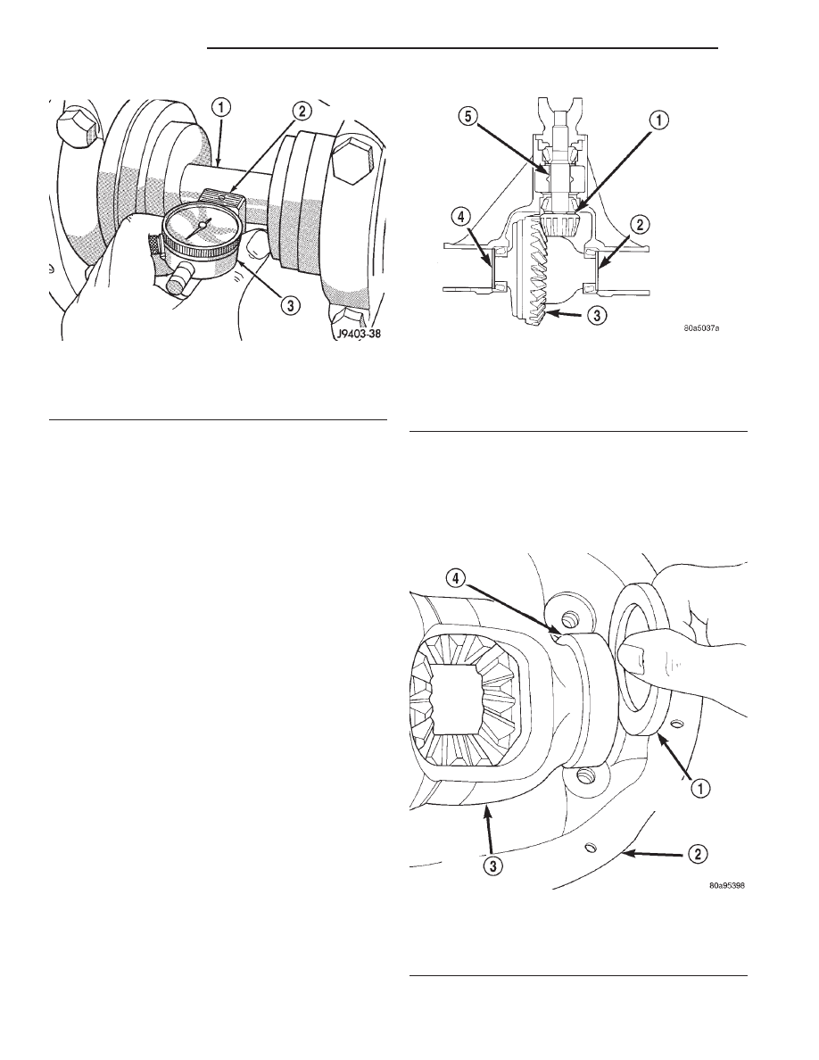
Fig. 70 Axle Adjustment Shim Locations

1 – PINION GEAR DEPTH SHIM
2 – DIFFERENTIAL BEARING SHIM-PINION GEAR SIDE
3 – RING GEAR
4 – DIFFERENTIAL BEARING SHIM-RING GEAR SIDE
5 – COLLAPSIBLE SPACER

Fig. 71 Insert Starting Point Shims

1 – SPECIAL TOOL 8107
2 – AXLE HOUSING
3 – DIFFERENTIAL CASE
4 – SPECIAL TOOL D-348

3 - 94

194 RBI AXLE

XJ

ADJUSTMENTS (Continued)

(6) Install the marked bearing caps in their correct

positions. Install and snug the bolts.

(7) Using a dead-blow type mallet, seat the differ-

ential dummy bearings to each side of the axle hous-
ing (Fig. 72) and (Fig. 73).

(8) Thread guide stud C-3288-B into rear cover

bolt hole below ring gear (Fig. 74).

(9) Attach dial indicator C-3339 to guide stud.

Position the dial indicator plunger on a flat surface
on a ring gear bolt head (Fig. 74).

(10) Push firmly and hold differential case to pin-

ion gear side of axle housing (Fig. 75).

(11) Zero dial indicator face to pointer.

(12) Push firmly and hold differential case to ring

gear side of the axle housing (Fig. 76).

(13) Record dial indicator reading.

Fig. 72 Seat Pinion Gear Dummy Side Bearing

1 – MALLET
2 – AXLE HOUSING
3 – DIFFERENTIAL CASE

Fig. 73 Seat Ring Gear Side Dummy Bearing

1 – AXLE HOUSING
2 – MALLET
3 – DIFFERENTIAL CASE

Fig. 74 Differential Side play Measurement

1 – DIFFERENTIAL CASE
2 – AXLE HOUSING
3 – SPECIAL TOOL C-3288–B
4 – SPECIAL TOOL C-3339

Fig. 75 Hold Differential Case and Zero Dial

Indicator

1 – FORCE DIFFERENTIAL CASE TO PINION GEAR SIDE
2 – SPECIAL TOOL C-3288–B
3 – SPECIAL TOOL C-3339
4 – ZERO DIAL INDICATOR FACE

XJ

194 RBI AXLE

3 - 95

ADJUSTMENTS (Continued)

(14) Add the dial indicator reading to the starting

point shim thickness to determine total shim thick-
ness to achieve zero differential end play.

(15) Add 0.008 in. (0.2 mm) to the zero end play

total. This new total represents the thickness of
shims to compress, or preload the new bearings when
the differential is installed.

(16) Rotate dial indicator out of the way on guide

stud.

(17) Remove differential case, dummy bearings,

and starting point shims from axle housing.

(18) Install pinion gear in axle housing. Install the

yoke and establish the correct pinion rotating torque.

(19) Install differential case and dummy bearings

in axle housing (without shims) and tighten retaining
cap bolts.

(20) Position the dial indicator plunger on a flat

surface between the ring gear bolt heads (Fig. 74).

(21) Push and hold differential case toward pinion

gear.

(22) Zero dial indicator face to pointer.
(23) Push and hold differential case to ring gear

side of the axle housing.

(24) Record dial indicator reading.
(25) Subtract 0.002 in. (0.05 mm) from the dial

indicator reading to compensate for backlash between
ring and pinion gears. This total is the thickness of
shim required to achieve proper backlash.

(26) Subtract the backlash shim thickness from

the total preload shim thickness. The remainder is
the shim thickness required on the pinion side of the
axle housing.

(27) Rotate dial indicator out of the way on guide

stud.

(28) Remove differential case and dummy bearings

from axle housing.

(29) Install new side bearing cones and cups on

differential case.

(30) Install spreader W-129-B, utilizing some com-

ponents of Adapter Set 6987, on axle housing and
spread axle opening enough to receive differential
case.

(31) Place side bearing shims in axle housing

against axle tubes.

(32) Install differential case in axle housing.
(33) Rotate the differential case several times to

seat the side bearings.

(34) Position the indicator plunger against a ring

gear tooth (Fig. 77).

(35) Push and hold ring gear upward while not

allowing the pinion gear to rotate.

(36) Zero dial indicator face to pointer.
(37) Push and hold ring gear downward while not

allowing the pinion gear to rotate. Dial indicator
reading should be between 0.12 mm (0.005 in.) and
0.20 mm (0.008 in.). If backlash is not within specifi-
cations transfer the necessary amount of shim thick-
ness from one side of the differential housing to the
other (Fig. 78).

Fig. 76 Hold Differential Case and Read Dial

Indicator

1 – READ DIAL INDICATOR
2 – FORCE DIFFERENTIAL CASE TO RING GEAR SIDE
3 – AXLE HOUSING

3 - 96

194 RBI AXLE

XJ

ADJUSTMENTS (Continued)

(38) Verify differential case and ring gear runout

by measuring ring to pinion gear backlash at eight
locations around the ring gear. Readings should not
vary more than 0.05 mm (0.002 in.). If readings vary
more than specified, the ring gear or the differential
case is defective.

After the proper backlash is achieved, perform the

Gear Contact Pattern Analysis procedure.

GEAR CONTACT PATTERN ANALYSIS

The ring gear and pinion teeth contact patterns

will show if the pinion depth is correct in the axle
housing. It will also show if the ring gear backlash
has been adjusted correctly. The backlash can be
adjusted within specifications to achieve desired
tooth contact patterns.

(1) Apply a thin coat of hydrated ferric oxide, or

equivalent, to the drive and coast side of the ring
gear teeth.

(2) Wrap, twist, and hold a shop towel around the

pinion yoke to increase the turning resistance of the
pinion. This will provide a more distinct contact pat-
tern.

(3) Using a boxed end wrench on a ring gear bolt,

Rotate the differential case one complete revolution
in both directions while a load is being applied from
shop towel.

The areas on the ring gear teeth with the greatest

degree of contact against the pinion teeth will squee-
gee the compound to the areas with the least amount
of contact. Note and compare patterns on the ring
gear teeth to Gear Tooth Contact Patterns chart (Fig.
79) and adjust pinion depth and gear backlash as
necessary.

Fig. 78 Backlash Shim Adjustment

Fig. 77 Ring Gear Backlash Measurement

1 – DIAL INDICATOR

XJ

194 RBI AXLE

3 - 97

ADJUSTMENTS (Continued)


Content   ..  34  35  36  37   ..