Jeep XJ. Manual - part 8


  Index      Jeep     Jeep XJ - service repair manual 2001 year


Search            


Content   ..  6  7  8  9   ..


Jeep XJ. Manual - part 8


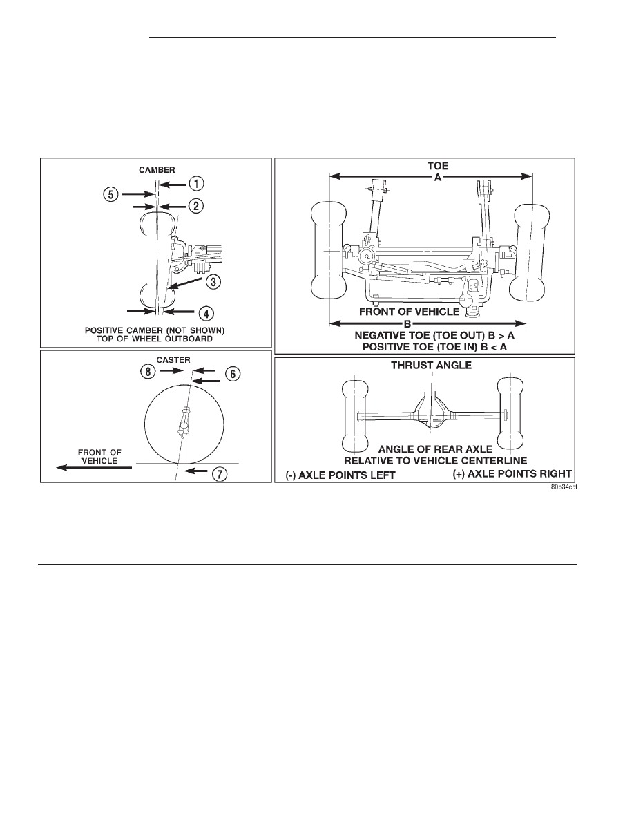
• THRUST ANGLE is the angle of the rear axle

relative to the centerline of the vehicle. Incorrect
thrust angle can cause off-center steering and exces-
sive tire wear. This angle is not adjustable, damaged
component(s) must be replaced to correct the thrust
angle.

Fig. 1 Wheel Alignment Measurements

1 – WHEEL CENTERLINE
2 – NEGATIVE CAMBER ANGLE
3 – PIVOT CENTERLINE
4 – SCRUB RADIUS

5 – TRUE VERTICAL
6 – KING PIN
7 – VERTICAL
8 – POSITIVE CASTER

2 - 2

SUSPENSION

XJ

DESCRIPTION AND OPERATION (Continued)

DIAGNOSIS AND TESTING

SUSPENSION AND STEERING SYSTEM

CONDITION

POSSIBLE CAUSES

CORRECTION

FRONT END NOISE

1. Loose or worn wheel bearings.

1. Adjust or replace wheel bearings.

2. Loose or worn steering or
suspension components.

2. Tighten or replace components as
necessary.

EXCESSIVE PLAY IN
STEERING

1. Loose or worn wheel bearings.

1. Adjust or replace wheel bearings.

2. Loose or worn steering or
suspension components.

2. Tighten or replace components as
necessary.

3. Loose or worn steering gear.

3. Adjust or replace steering gear.

FRONT WHEELS SHIMMY

1. Loose or worn wheel bearings.

1. Adjust or replace wheel bearings.

2. Loose or worn steering or
suspension components.

2. Tighten or replace components as
necessary.

3. Tires worn or out of balance.

3. Replace or balance tires.

4. Alignment.

4. Align vehicle to specifications.

5. Leaking steering dampener.

5. Replace steering dampener.

VEHICLE INSTABILITY

1. Loose or worn wheel bearings.

1. Adjust or replace wheel bearings.

2. Loose or worn steering or
suspension components.

2. Tighten or replace components as
necessary.

3. Tire pressure.

3. Adjust tire pressure.

4. Alignment.

4. Align vehicle to specifications.

EXCESSIVE STEERING
EFFORT

1. Loose or worn steering gear.

1. Adjust or replace steering gear.

2. Power steering fluid low.

2. Add fluid and repair leak.

3. Column coupler binding.

3. Replace coupler.

4. Tire pressure.

4. Adjust tire pressure.

5. Alignment.

5. Align vehicle to specifications.

VEHICLE PULLS TO ONE
SIDE DURING BRAKING

1. Uneven tire pressure.

1. Adjust tire pressure.

2. Worn brake components.

2. Repair brakes as necessary.

3. Air in brake line.

3. Repair as necessary.

VEHICLE LEADS OR
DRIFTS FROM STRAIGHT
AHEAD DIRECTION ON
UNCROWNED ROAD

1. Radial tire lead.

1. Cross front tires.

2. Brakes dragging.

2. Repair brake as necessary.

3. Weak or broken spring.

3. Replace spring.

4. Uneven tire pressure.

4. Adjust tire pressure.

5. Wheel Alignment.

5. Align vehicle.

6. Loose or worn steering or
suspension components.

6. Repair as necessary.

7. Cross caster out of spec.

7. Align vehicle.

XJ

SUSPENSION

2 - 3

CONDITION

POSSIBLE CAUSES

CORRECTION

KNOCKING, RATTLING
OR SQUEAKING

1. Worn shock bushings.

1. Replace shock.

2. Loose, worn or bent steering/
suspension components.

2. Inspect, tighten or replace components
as necessary.

3. Shock valve.

3. Replace shock.

IMPROPER TRACKING

1. Loose, worn or bent track bar.

1. Inspect, tighten or replace component as
necessary.

2. Loose, worn or bent steering/
suspension components.

2. Inspect, tighten or replace components
as necessary.

SERVICE PROCEDURES

PRE-ALIGNMENT

Before starting wheel alignment, the following

inspection and necessary corrections must be com-
pleted. Refer to Suspension and Steering System
Diagnosis Chart for additional information.

(1) Inspect tires for size and tread wear.
(2) Set tire air pressure.
(3) Inspect front wheel bearings for wear.
(4) Inspect front wheels for excessive radial or lat-

eral runout and balance.

(5) Inspect ball studs, linkage pivot points and

steering gear for looseness, roughness or binding.

(6) Inspect suspension components for wear and

noise.

WHEEL ALIGNMENT

Before each alignment reading, the vehicle should

be jounced (rear first, then front). Grasp each
bumper at the center and jounce the vehicle up and
down several times. Always release the bumper in
the down position. Set the front end alignment to
specifications with the vehicle at its NORMAL RIDE
HEIGHT.

CAMBER

The wheel camber angle is preset. This angle is not

adjustable and cannot be altered.

CASTER

Before checking the caster of the front axle for cor-

rect angle, be sure the axle is not bent or twisted.

Road test the vehicle, make left and right turns. If

the steering wheel returns to the center position
unassisted, the caster angle is correct. If steering
wheel does not return toward the center position
unassisted, an incorrect caster angle is probable.

Caster can be adjusted by installing the appropri-

ate size shims (Fig. 2).

NOTE: Changing caster angle will also change the
front propeller shaft angle. The propeller shaft
angle has priority over caster. Refer to Group 3 Dif-
ferential & Driveline for additional information.

TOE POSITION (LHD)

NOTE: The wheel toe position adjustment is the
final adjustment. The engine must remain running
during the entire toe position adjustment.

(1) Start the engine and turn wheels both ways

before straightening the wheels. Secure the steering
wheel with the front wheels in the straight-ahead
position.

(2) Loosen the adjustment sleeve clamp bolts (Fig.

3).

(3) Adjust the right wheel toe position with the

drag link. Turn the sleeve until the right wheel is at
correct TOE-IN specifications. Position the clamp

Fig. 2 Caster Adjustment

1 – SHIM
2 – SUSPENSION ARM

2 - 4

SUSPENSION

XJ

DIAGNOSIS AND TESTING (Continued)

bolts as shown (Fig. 4) and tighten to 49 N·m (36 ft.
lbs.).

NOTE: Make sure the toe setting does not change
during clamp tightening.

(4) Adjust the left wheel toe position with the tie

rod. Turn the sleeve until the left wheel is at specifi-
cations. Position the clamp bolts as shown (Fig. 4)
and tighten to 27 N·m (20 ft. lbs.).

NOTE: Make sure the toe setting does not change
during clamp tightening.

(5) Verify the right toe setting and turn off engine.
(6) Road test the vehicle on a flat level road to ver-

ify the steering wheel is centered.

NOTE: Once the toe setting is correct, the steering
wheel can be re-centered by adjusting only the drag
link.

TOE POSITION (RHD)

NOTE: The wheel toe position adjustment is the
final adjustment. The engine must remain running
during the entire toe position adjustment.

(1) Start the engine and turn wheels both ways

before straightening the wheels. Secure the steering

wheel with the front wheels in the straight-ahead
position.

(2) Loosen the adjustment sleeve clamp bolts (Fig.

5).

(3) Adjust the left wheel toe position with the drag

link. Turn the sleeve until the left wheel is at the
correct TOE-IN specifications. Position the clamp
bolts to their original position and tighten to 49 N·m
(36 ft. lbs.).

Fig. 3 Steering Linkage (LHD)

1 – PITMAN ARM
2 – ADJUSTMENT SLEEVE
3 – DRAG LINK

4 – TIE ROD
5 – STEERING DAMPENER

Fig. 4 Drag Link and Tie Rod Clamp (LHD)

1 – TIE ROD CLAMP
2 – DRAG LINK CLAMPS

XJ

SUSPENSION

2 - 5

SERVICE PROCEDURES (Continued)


Content   ..  6  7  8  9   ..