Jeep Wrangler TJ. Manual - part 597


  Index      Jeep     Jeep Wrangler TJ - service repair manual 2005 year


Search            


Content   ..  595  596  597  598   ..


Jeep Wrangler TJ. Manual - part 597


connect the demister ducts from the demister outlets
and the defroster duct as necessary (Fig. 37).

DEMISTER OUTLETS

NOTE: Take the proper precautions to protect the
front face of the instrument panel from cosmetic
damage while performing this procedure.

(1) Remove the instrument panel assembly and

place it on a workbench (Refer to 23 - BODY/IN-
STRUMENT

PANEL/INSTRUMENT

PANEL

ASSEMBLY - REMOVAL)

(2) Disconnect the demister ducts from the demis-

ter outlets as necessary (Fig. 38).

(3) Remove the screw that secures each demister

outlet to the instrument panel duct as necessary.

(4) Remove the demister outlets from the instru-

ment panel as necessary.

INSTALLATION

NOTE: The two demister ducts can be serviced
without removing the instrument panel. However, if
either of the demister outlets require servicing, the
instrument panel must be removed.

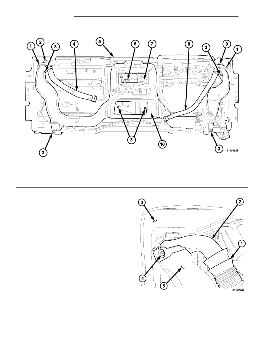
Fig. 37 Demister Ducts - IP Removed for Clarity

1 - SCREW (2)
2 - RH DEMISTER OUTLET
3 - SCREW (10)
4 - RH DEMISTER DUCT
5 - INSTRUMENT PANEL

6 - RADIO REAR SUPPORT BRACKET
7 - RADIO
8 - LH DEMISTER DUCT
9 - LH DEMISTER OUTLET
10 - INSTRUMENT PANEL DUCT

Fig. 38 Demister Outlet - Right Side shown, Left

Side similar

1 - DEMISTER HOSE (2)
2 - DEMISTER OUTLET (2)
3 - INSTRUMENT PANEL
4 - SCREW (2)
5 - INSTRUMENT PANEL DUCT

24 - 54

DISTRIBUTION

TJ

INSTRUMENT PANEL DEMISTER DUCTS (Continued)

DEMISTER DUCTS

(1) Reach through the glove box opening and/or

the cluster opening of the instrument panel to con-
nect the demister ducts to the demister outlets and
the defroster duct as necessary.

(2) If removed, install the top cover, knee blocker

and instrument cluster (Refer to 23 - BODY/IN-
STRUMENT PANEL/INSTRUMENT PANEL TOP
COVER - INSTALLATION), (Refer to 23 - BODY/IN-
STRUMENT PANEL/KNEE BLOCKER - INSTALLA-
TION)

and

(Refer

to

8

-

ELECTRICAL/

INSTRUMENT CLUSTER - INSTALLATION).

(3) If removed, install the glove box (Refer to 23 -

BODY/INSTRUMENT

PANEL/GLOVE

BOX

-

INSTALLATION).

(4) Reconnect the negative battery cable.

DEMISTER OUTLETS

(1) Position the demister outlets into the instru-

ment panel as necessary.

(2) Install the screw that secures each demister

outlet to the instrument panel duct as necessary.

(3) Connect the demister ducts to the demister

outlets as necessary.

(4) Install the instrument panel assembly (Refer to

23 - BODY/INSTRUMENT PANEL/INSTRUMENT
PANEL ASSEMBLY - INSTALLATION).

INSTRUMENT PANEL DUCTS

REMOVAL

WARNING: On vehicles equipped with airbags, dis-
able the airbag system before attempting any steer-
ing wheel, steering column, or instrument panel
component diagnosis or service. Disconnect and
isolate the battery negative (ground) cable, then
wait two minutes for the airbag system capacitor to
discharge before performing further diagnosis or
service. This is the only sure way to disable the air-
bag system. Failure to take the proper precautions
could result in accidental airbag deployment and
possible personal injury or death.

NOTE: The air ducts for the instrument panel out-
lets are integral to each other and cannot be ser-
viced separately.

NOTE: Take the proper precautions to protect the
front face of the instrument panel from cosmetic
damage while performing this procedure.

(1) Disconnect and isolate the negative battery

cable.

(2) Remove the instrument panel and place it on a

workbench (Refer to 23 - BODY/INSTRUMENT PAN-
EL/INSTRUMENT

PANEL

ASSEMBLY

-

REMOVAL).

(3) Remove the center bezel from the instrument

panel (Refer to 23 - BODY/INSTRUMENT PANEL/
INSTRUMENT

PANEL

CENTER

BEZEL

-

REMOVAL).

(4) Remove the accessory switch bezel, A/C-heater

control, radio and radio rear support bracket from
the instrument panel (Refer to 23 - BODY/INSTRU-
MENT

PANEL/ACCESSORY

SWITCH

BEZEL

-

REMOVAL), (Refer to 24 - HEATING & AIR CONDI-
TIONING/CONTROLS/A/C HEATER CONTROL -
REMOVAL) and (Fig. 39) (Refer to 8 - ELECTRICAL/
AUDIO/RADIO - REMOVAL).

(5) Remove the demister ducts and the demister

outlets (Refer to 24 - HEATING & AIR CONDITION-
ING/DISTRIBUTION/INSTRUMENT

PANEL

DEMISTER DUCTS - REMOVAL).

(6) Disconnect the instrument panel wire harness

connectors from the left and right side courtesy
lamps located at the bottom of the instrument panel.

(7) Disengage the instrument panel wire harness

retainers from the instrument panel duct and posi-
tion the wire harness out of the way.

(8) Remove the ten screws that secure the instru-

ment panel duct to the instrument panel and remove
the duct.

TJ

DISTRIBUTION

24 - 55

INSTRUMENT PANEL DEMISTER DUCTS (Continued)

INSTALLATION

(1) Position the instrument panel duct into the

instrument panel.

(2) Install the ten screws that secure the instru-

ment panel duct to the instrument panel. Tighten the
screws to 2 N·m (17 in. lbs.).

(3) Engage the instrument panel wire harness

retainers to the instrument panel duct and connect
the wire harness to the left and right courtesy lamps.

(4) Install the demister outlets and the demister

ducts (Refer to 24 - HEATING & AIR CONDITION-
ING/DISTRIBUTION/INSTRUMENT

PANEL

DEMISTER DUCTS - INSTALLATION.

(5) Install the accessory switch bezel, A/C-heater

control and the radio and the radio rear support

bracket into the instrument panel (Refer to 23 -
BODY/INSTRUMENT

PANEL/ACCESSORY

SWITCH BEZEL - INSTALLATION), (Refer to 24 -
HEATING & AIR CONDITIONING/CONTROLS/A/C
HEATER CONTROL - INSTALLATION) and (Refer
to 8 - ELECTRICAL/AUDIO/RADIO - INSTALLA-
TION).

(6) Install the center bezel onto the instrument

panel (Refer to 23 - BODY/INSTRUMENT PANEL/
INSTRUMENT PANEL CENTER BEZEL - INSTAL-
LATION).

(7) Install the instrument panel (Refer to 23 -

BODY/INSTRUMENT

PANEL/INSTRUMENT

PANEL ASSEMBLY - INSTALLATION).

(8) Reconnect the negative battery cable.

Fig. 39 Instrument Panel Duct - LHD shown, RHD typical

1 - SCREW (2)
2 - RH DEMISTER OUTLET
3 - SCREW (10)
4 - RH DEMISTER DUCT
5 - INSTRUMENT PANEL

6 - RADIO REAR SUPPORT BRACKET
7 - RADIO
8 - LH DEMISTER DUCT
9 - LH DEMISTER OUTLET
10 - INSTRUMENT PANEL DUCT

24 - 56

DISTRIBUTION

TJ

INSTRUMENT PANEL DUCTS (Continued)

PLUMBING

TABLE OF CONTENTS

page

page

PLUMBING

DESCRIPTION

. . . . . . . . . . . . . . . . . . . . . . . . . 58

OPERATION

. . . . . . . . . . . . . . . . . . . . . . . . . . . 58

WARNINGS

. . . . . . . . . . . . . . . . . . . . . . . . . . . 58

CAUTIONS

. . . . . . . . . . . . . . . . . . . . . . . . . . . . 58

DIAGNOSIS AND TESTING

REFRIGERANT SYSTEM LEAKS

. . . . . . . . . . 59

STANDARD PROCEDURE

REFRIGERANT SYSTEM SERVICE

EQUIPMENT . . . . . . . . . . . . . . . . . . . . . . . . . 60

REFRIGERANT SYSTEM CHARGE LEVEL

. . 61

REFRIGERANT SYSTEM RECOVERY

. . . . . . 62

REFRIGERANT SYSTEM EVACUATE

. . . . . . 62

REFRIGERANT SYSTEM CHARGE

. . . . . . . . 63

A/C COMPRESSOR

DESCRIPTION

A/C COMPRESSOR

. . . . . . . . . . . . . . . . . . . . 64

HIGH PRESSURE RELIEF VALVE

. . . . . . . . . 64

OPERATION

A/C COMPRESSOR

. . . . . . . . . . . . . . . . . . . . 64

HIGH PRESSURE RELIEF VALVE

. . . . . . . . . 64

DIAGNOSIS AND TESTING

A/C COMPRESSOR NOISE

. . . . . . . . . . . . . . 64

REMOVAL

2.4L ENGINE

. . . . . . . . . . . . . . . . . . . . . . . . . 65

4.0L ENGINE

. . . . . . . . . . . . . . . . . . . . . . . . . 66

INSTALLATION

2.4L ENGINE

. . . . . . . . . . . . . . . . . . . . . . . . . 67

4.0L ENGINE

. . . . . . . . . . . . . . . . . . . . . . . . . 67

A/C CONDENSER

DESCRIPTION

. . . . . . . . . . . . . . . . . . . . . . . . . 68

OPERATION

. . . . . . . . . . . . . . . . . . . . . . . . . . . 68

REMOVAL

. . . . . . . . . . . . . . . . . . . . . . . . . . . . . 68

INSTALLATION

. . . . . . . . . . . . . . . . . . . . . . . . . 69

A/C DISCHARGE LINE

DESCRIPTION

. . . . . . . . . . . . . . . . . . . . . . . . . 70

REMOVAL

2.4L ENGINE

. . . . . . . . . . . . . . . . . . . . . . . . . 70

4.0L ENGINE

. . . . . . . . . . . . . . . . . . . . . . . . . 71

INSTALLATION

2.4L ENGINE

. . . . . . . . . . . . . . . . . . . . . . . . . 71

4.0L ENGINE

. . . . . . . . . . . . . . . . . . . . . . . . . 72

A/C EVAPORATOR

DESCRIPTION

. . . . . . . . . . . . . . . . . . . . . . . . . 72

OPERATION

. . . . . . . . . . . . . . . . . . . . . . . . . . . 73

REMOVAL

. . . . . . . . . . . . . . . . . . . . . . . . . . . . . 73

INSTALLATION

. . . . . . . . . . . . . . . . . . . . . . . . . 73

A/C ORIFICE TUBE

DESCRIPTION

. . . . . . . . . . . . . . . . . . . . . . . . . 73

OPERATION

. . . . . . . . . . . . . . . . . . . . . . . . . . . 74

DIAGNOSIS AND TESTING

A/C ORIFICE TUBE

. . . . . . . . . . . . . . . . . . . . 74

ACCUMULATOR

DESCRIPTION

. . . . . . . . . . . . . . . . . . . . . . . . . 74

OPERATION

. . . . . . . . . . . . . . . . . . . . . . . . . . . 74

REMOVAL

. . . . . . . . . . . . . . . . . . . . . . . . . . . . . 75

INSTALLATION

. . . . . . . . . . . . . . . . . . . . . . . . . 76

HEATER CORE

DESCRIPTION

. . . . . . . . . . . . . . . . . . . . . . . . . 76

OPERATION

. . . . . . . . . . . . . . . . . . . . . . . . . . . 76

REMOVAL

. . . . . . . . . . . . . . . . . . . . . . . . . . . . . 77

INSTALLATION

. . . . . . . . . . . . . . . . . . . . . . . . . 77

LIQUID LINE

DESCRIPTION

. . . . . . . . . . . . . . . . . . . . . . . . . 77

REMOVAL

. . . . . . . . . . . . . . . . . . . . . . . . . . . . . 77

INSTALLATION

. . . . . . . . . . . . . . . . . . . . . . . . . 78

REFRIGERANT

DESCRIPTION

. . . . . . . . . . . . . . . . . . . . . . . . . 79

OPERATION

. . . . . . . . . . . . . . . . . . . . . . . . . . . 79

REFRIGERANT LINE COUPLER

DESCRIPTION

. . . . . . . . . . . . . . . . . . . . . . . . . 79

OPERATION

. . . . . . . . . . . . . . . . . . . . . . . . . . . 80

REMOVAL

. . . . . . . . . . . . . . . . . . . . . . . . . . . . . 80

INSTALLATION

. . . . . . . . . . . . . . . . . . . . . . . . . 81

REFRIGERANT OIL

DESCRIPTION

. . . . . . . . . . . . . . . . . . . . . . . . . 81

OPERATION

. . . . . . . . . . . . . . . . . . . . . . . . . . . 81

STANDARD PROCEDURE

REFRIGERANT OIL LEVEL

. . . . . . . . . . . . . . 81

SERVICE PORT VALVE CORE

DESCRIPTION

. . . . . . . . . . . . . . . . . . . . . . . . . 82

REMOVAL

. . . . . . . . . . . . . . . . . . . . . . . . . . . . . 82

INSTALLATION

. . . . . . . . . . . . . . . . . . . . . . . . . 82

SUCTION LINE

DESCRIPTION

. . . . . . . . . . . . . . . . . . . . . . . . . 83

REMOVAL

. . . . . . . . . . . . . . . . . . . . . . . . . . . . . 83

INSTALLATION

. . . . . . . . . . . . . . . . . . . . . . . . . 84

TJ

PLUMBING

24 - 57


Content   ..  595  596  597  598   ..