Jeep Wrangler TJ. Manual - part 587


  Index      Jeep     Jeep Wrangler TJ - service repair manual 2005 year


Search            


Content   ..  585  586  587  588   ..


Jeep Wrangler TJ. Manual - part 587


(6) Remove the screw and retainer from the clutch

coil lead wire harness on the compressor front hous-
ing.

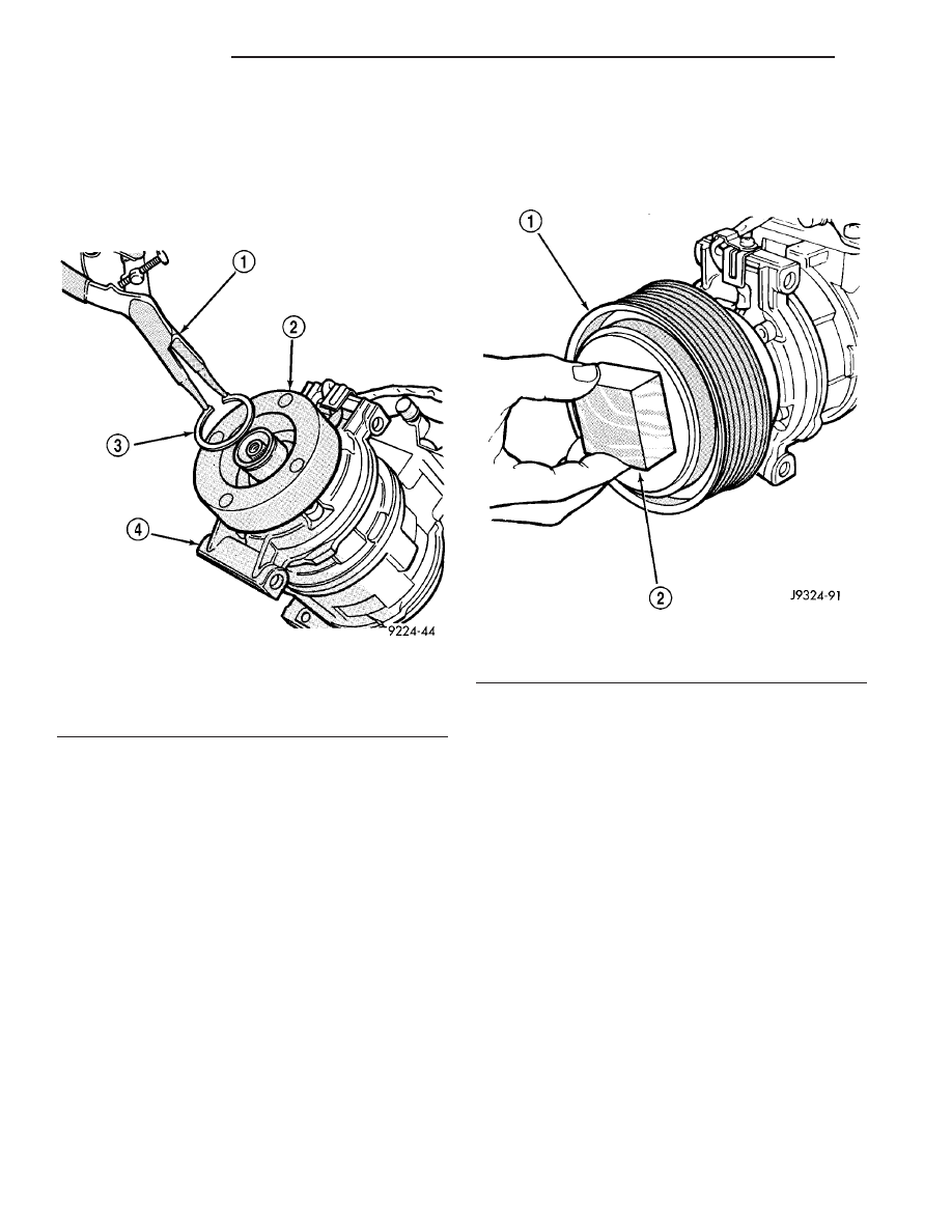
(7) Remove the external snap ring that secures the

compressor clutch coil to the nose of the compressor
front housing with snap ring pliers and slide the coil
assembly off of the compressor (Fig. 7).

INSTALLATION

(1) Align the dowel pin on the back of the clutch

field coil with the hole in the compressor front hous-
ing and press the field coil into place over the nose of
the compressor.

(2) Install the clutch coil lead wire harness retain-

ing clip on the compressor front housing and tighten
the retaining screw.

(3) Install the clutch field coil and snap ring with

snap ring pliers (Special Tool C-4574). The bevel side
of the snap ring must be facing outward. Also, both
eyelets of the snap ring must be to the right or left of
the pin on the compressor. Press in on the snap ring
to be certain that it is properly seated in the groove.

CAUTION: If the snap ring is not fully seated in the
groove it will vibrate out, resulting in a clutch fail-
ure and severe damage to the front housing of the
compressor.

(4) Install the pulley assembly onto the compres-

sor. If necessary, place a block of wood on the friction
surface and tap gently with a hammer (Fig. 8).

CAUTION: Do not mar the pulley friction surface.

(5) Install the pulley assembly retaining snap ring

(bevel side outward) with snap ring pliers (Special
Tool C-4574). Press in on the snap ring to be certain
that it is properly seated in the groove.

(6) If the original clutch plate assembly and pulley

assembly are to be reused, the old shim(s) can be
used. If not, place a stack of shim(s) equal to the old
shim(s) on the shaft against the shoulder.

(7) Install the clutch plate assembly onto the

shaft.

NOTE: The shims may compress after tightening
the shaft bolt. Check the air gap in four or more
places to verify the air gap is still correct. Spin the
pulley before performing a final check of the air
gap.

(8) With the clutch plate assembly tight against

the shim(s), measure the air gap between the clutch
plate and the pulley face with feeler gauges. The air
gap should be between 0.35 to 0.65 mm (0.014 to
0.026 in.). If the proper air gap is not obtained, add
or subtract shims as needed until the desired air gap
is obtained.

Fig. 7 Clutch Coil Snap Ring

1 - SNAP RING PLIERS
2 - CLUTCH COIL
3 - SNAP RING
4 - COMPRESSOR

Fig. 8 Pulley Assembly - Install

1 - PULLEY ASSEMBLY
2 - WOOD BLOCK

24 - 14

CONTROLS

TJ

A/C COMPRESSOR CLUTCH (Continued)

(9) Install the compressor shaft bolt. Tighten the

bolt to 13 N·m (115 in. lbs.).

(10) Install the accessory drive belt (Refer to 7 -

COOLING/ACCESSORY

DRIVE/DRIVE

BELTS

-

INSTALLATION).

(11) Reconnect the negative battery cable.

A/C CLUTCH RELAY

DESCRIPTION

The A/C clutch relay (Fig. 9) is a International

Standards Organization (ISO) micro-relay. Relays
conforming to the ISO specifications have common
physical dimensions, current capacities, terminal
functions and patterns. The ISO micro-relay terminal
functions are the same as a conventional ISO relay.
However, the ISO micro-relay terminal pattern (or
footprint) is different, the current capacity is lower,
and the physical dimensions are smaller than those
of the conventional ISO relay.

The A/C clutch relay is located in the power distri-

bution center (PDC) in the engine compartment.

OPERATION

The A/C clutch relay is an electromechanical

switch that uses a low current input controlled by
the powertrain control module (PCM) to control the
high current output to the A/C clutch field coil. The
movable, common feed relay contact is held against
the fixed, normally closed relay contact by spring
pressure. When the electromagnetic relay coil is
energized, it draws the movable common feed relay
contact away from the fixed, normally closed relay
contact and, holds it against the fixed, normally open
relay contact. This action allows high current to flow
to the A/C clutch field coil.

When the relay coil is de-energized, spring pres-

sure returns the movable relay contact back against
the fixed, normally closed contact point. The resistor
or diode is connected in parallel with the relay coil,
and helps to dissipate voltage spikes and electromag-
netic interference that can be generated as the elec-
tromagnetic field of the relay coil collapses.

The A/C clutch relay terminals are connected to

the vehicle electrical system through a receptacle in
the power distribution center (PDC). The inputs and
outputs of the A/C clutch relay include:

• The common feed terminal (A10) receives bat-

tery current through a fuse in the PDC at all times.

• The coil ground terminal (A8) receives a ground

input from the PCM through the A/C clutch relay
control circuit only when the PCM electronically
pulls the control circuit to ground.

• The coil battery terminal (A6) receives battery

current through a fuse in the fuse block only when
the ignition switch is in the Run or Start position.

• The normally open terminal (A9) provides bat-

tery current to the A/C clutch coil through the A/C
clutch relay only when the A/C clutch relay coil is
energized.

• The normally closed terminal (87A) is not con-

nected to any circuit in this application, but provides
a battery current output only when the A/C clutch
relay coil is de-energized.

The A/C clutch relay cannot be repaired and, if

faulty or damaged, it must be replaced. Refer to the
appropriate wiring information for diagnosis and
testing of the ISO-standard micro-relay and for com-
plete HVAC wiring diagrams.

Fig. 9 A/C Compressor Clutch Relay

30 - COMMON FEED
85 - COIL GROUND
86 - COIL BATTERY
87 - NORMALLY OPEN
87A - NORMALLY CLOSED

TJ

CONTROLS

24 - 15

A/C COMPRESSOR CLUTCH (Continued)

REMOVAL

(1) Disconnect and isolate the battery negative

cable.

(2) Remove the cover from the power distribution

center (PDC) (Fig. 10) located in the engine compart-
ment.

NOTE: Refer to the fuse and relay layout map on
the inside of the PDC cover for A/C clutch relay
location.

(3) Remove the A/C clutch relay from the PDC.

INSTALLATION

NOTE: Refer to the fuse and relay layout map on
the inside of the power distribution center (PDC)
cover for A/C clutch relay location.

(1) Position the A/C clutch relay into the receptacle

of the PDC.

(2) Align the A/C clutch relay terminals with the

terminal cavities in the PDC receptacle and push
down firmly on the relay until the terminals are fully
seated.

(3) Close the cover of the PDC.
(4) Reconnect the negative battery cable.

A/C HEATER CONTROL

DESCRIPTION

The A/C-heater control (Fig. 11) for both the man-

ual temperature control (MTC) single zone heating-
only

and

the

heating-A/C

system

allows

one

temperature setting for the entire vehicle. All con-
trols are identified by ISO graphic symbols.

The A/C-heater control is located in the instrument

panel and contains:

• a rotary control knob for blower fan speed selec-

tion.

• a rotary control knob for recirculation and mode

control of the discharged air.

• a rotary control knob for temperature control of

the discharged air and turning the heating-A/C sys-
tem off.

The A/C-heater control cannot be repaired and, if

faulty or damaged, it must be replaced. The blower
motor and mode control switch, control knobs and
illumination lamps are available for service replace-
ment.

Fig. 10 Power Distribution Center - LHD shown,

RHD similar

1 - BATTERY POSITIVE CABLE
2 - BATTERY NEGATIVE CABLE
3 - DASH PANEL
4 - INNER FENDER
5 - POWER DISTRIBUTION CENTER (PDC)
6 - NUT

Fig. 11 A/C-Heater Control - Typical

1 - BLOWER SPEED CONTROL
2 - TEMPERATURE SELECT COPNTROL
3 - MODE SELECT CONTROL

24 - 16

CONTROLS

TJ

A/C CLUTCH RELAY (Continued)

DIAGNOSIS AND TESTING

VACUUM CONTROL SYSTEM

Vacuum control is used to operate the mode-air

doors within the HVAC housing. Testing the opera-
tion of the heating-only and heating-A/C system
mode control will determine if the vacuum and
mechanical controls are functioning. However, it is
possible that a vacuum control system that operates
correctly at engine idle (high engine vacuum) may
not function properly at high engine speeds or loads
(low engine vacuum). This can be caused by leaks
within the vacuum system, or a faulty vacuum check
valve.

A vacuum system test will help to identify the

source of poor vacuum system performance or vac-
uum system leaks. Before starting this test, stop the
engine and make certain that the problem is not a
disconnected vacuum supply line at the engine intake
manifold vacuum tap or at the vacuum reservoir.

Use an adjustable vacuum test set (Special Tool

C-3707-B) and a suitable vacuum pump to test the
HVAC vacuum control system. With a finger placed
over the end of the vacuum test hose probe (Fig. 12),
adjust the bleed valve on the test set gauge to obtain
a vacuum of exactly 27 kPa (8 in. Hg.). Release and
block the end of the probe several times to verify that
the vacuum reading returns to the exact 27 kPa (8
in. Hg.) setting. Otherwise, a false reading will be
obtained during testing.

VACUUM CHECK VALVE

(1) Remove the vacuum check valve. The valve is

located in the (black) vacuum supply tube at the
intake manifold vacuum tap.

(2) Connect the test set vacuum supply hose to the

A/C-heater control side of the vacuum check valve.
When connected to this side of the check valve, no
vacuum should pass and the test set gauge should
return to the 27 kPa (8 in. Hg.) setting. If OK, go to
Step 3. If not OK, replace the faulty vacuum check
valve.

(3) Connect the test set vacuum supply hose to the

engine vacuum side of the vacuum check valve.
When connected to this side of the check valve, vac-
uum should flow through the check valve without
restriction. If not OK, replace the faulty vacuum
check valve.

A/C HEATER CONTROLS

(1) Connect the test set vacuum probe to the heat-

er-A/C vacuum supply (black) tube in the engine
compartment. Position the test set gauge so that it
can be viewed from the passenger compartment.

(2) Place the A/C-heater mode control in each

mode position, one position at a time, and pause
after each selection. The test set gauge should return
to the 27 kPa (8 in. Hg.) setting shortly after each
selection is made. If not OK, a component or vacuum
line in the vacuum circuit of the selected mode has a
leak. See the procedure in Locating Vacuum Leaks.

LOCATING VACUUM LEAKS

WARNING: On vehicles equipped with airbags, dis-
able the airbag system before attempting any steer-
ing wheel, steering column, or instrument panel
component diagnosis or service. Disconnect and
isolate the battery negative (ground) cable, then
wait two minutes for the airbag system capacitor to
discharge before performing further diagnosis or
service. This is the only sure way to disable the air-
bag system. Failure to take the proper precautions
could result in accidental airbag deployment and
possible personal injury or death.

CAUTION: Do not use lubricant on the switch ports
or in the holes of the connector, as lubricant will
ruin the vacuum valve in the switch. A drop of clean
water in the connector holes will help the connector
slide onto the switch ports.

Fig. 12 Adjust Vacuum Test Bleed Valve

1 - VACUUM PUMP TOOL C-4289
2 - VACUUM TEST SET C-3707
3 - BLEED VALVE
4 - PROBE

TJ

CONTROLS

24 - 17

A/C HEATER CONTROL (Continued)


Content   ..  585  586  587  588   ..