Jeep Wrangler TJ. Manual - part 490


  Index      Jeep     Jeep Wrangler TJ - service repair manual 2005 year


Search            


Content   ..  488  489  490  491   ..


Jeep Wrangler TJ. Manual - part 490


DIAGNOSIS AND TESTING - CLUTCH AIR
PRESSURE TESTS

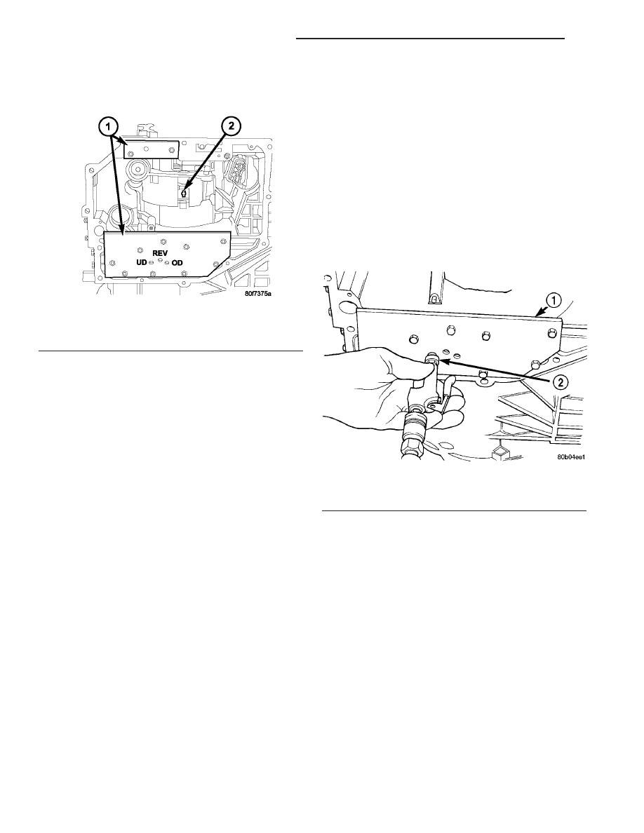
Inoperative clutches can be located by substituting

air pressure for fluid pressure. The clutches may be
tested by applying air pressure to their respective
passages after the valve body has been removed. Use
Special Tool 6599-1 (1) and 6599-2 (1) to perform test
(Fig. 9).

To make air pressure tests, proceed as follows:

NOTE: The compressed air supply must be free of
all dirt and moisture. Use a pressure of 30 psi.

(1) Remove oil pan and valve body. (Refer to 21 -

TRANSMISSION/AUTOMATIC

-

42RLE/VALVE

BODY - REMOVAL)

(2) Apply air pressure to the holes in the special

tool (1), one at a time.

(3) Listen for the clutch to apply. It will give a

slight thud sound. If a large amount of air is heard
escaping, the transmission must be removed from
vehicle, disassembled and all seals inspected.

2/4 CLUTCH

Apply air pressure to the feed hole located on the

2/4 clutch retainer (2). Look in the area where the
2/4 piston contacts the first separator plate and
watch carefully for the 2/4 piston to move rearward.
The piston should return to its original position after
the air pressure is removed.

OVERDRIVE CLUTCH

Apply air pressure to the overdrive clutch apply

passage and watch for the push/pull piston to move
forward. The piston should return to its starting
position when the air pressure is removed.

REVERSE CLUTCH

Apply air pressure to the reverse clutch apply pas-

sage and watch for the push/pull piston to move rear-
ward. The piston should return to its starting
position when the air pressure is removed.

LOW/REVERSE CLUTCH

Apply air pressure to the low/reverse clutch feed

hole passage. Look in the area where the low/reverse
piston contacts the first separator plate. Watch care-
fully for the piston to move forward. The piston
should return to its original position after the air
pressure is removed.

UNDERDRIVE CLUTCH

Because this clutch piston cannot be seen, its oper-

ation is checked by function. Air pressure is applied
to the low/reverse or the 2/4 clutches. This locks the
output shaft. Use a piece of rubber hose wrapped
around the input shaft and a pair of clamp-on pliers
to turn the input shaft. Next apply air pressure (Fig.
10) to the underdrive clutch. The input shaft should
not rotate with hand torque. Release the air pressure
and confirm that the input shaft will rotate.

DIAGNOSIS AND TESTING - FLUID LEAKAGE

FLUID LEAKAGE - TORQUE CONVERTER HOUSING
AREA

When diagnosing converter housing fluid leaks,

three actions must be taken before repair:

(1) Verify proper transmission fluid level.
(2) Verify that the leak originates from the con-

verter housing area and is transmission fluid.

(3) Determine the true source of the leak.

Fig. 9 Air Pressure Test Plate

1 - AIR PRESSURE TEST PLATES
2 - 2/4 CLUTCH RETAINER HOLE

Fig. 10 Testing Underdrive Clutch

1 - AIR PRESSURE TEST PLATE 6599-1
2 - AIR NOZZLE

21 - 50

AUTOMATIC TRANSMISSION - 42RLE

TJ

AUTOMATIC TRANSMISSION - 42RLE (Continued)

Fluid leakage at or around the torque converter

area (Fig. 11) may originate from an engine oil leak.
The area should be examined closely. Factory fill
fluid is red and, therefore, can be distinguished from
engine oil.

Some suspected converter housing fluid leaks may

not be leaks at all. They may only be the result of
residual fluid in the converter housing, or excess
fluid spilled during factory fill, or fill after repair.
Converter

housing

leaks

have

several

potential

sources. Through careful observation, a leak source
can be identified before removing the transmission
for repair.

Pump seal leaks tend to move along the drive hub

(Fig. 11) and onto the rear of the converter. Pump
o-ring or pump body leaks follow the same path as a
seal leak. Pump attaching bolt leaks are generally
deposited on the inside of the converter housing and
not on the converter itself. Pump seal or gasket leaks
(Fig. 11)usually travel down the inside of the con-
verter housing.

TORQUE CONVERTER LEAKAGE

Possible sources of torque converter leakage are:
• Torque converter weld leaks at the outside diam-

eter weld. (Fig. 12)

• Torque converter hub weld. (Fig. 12)

STANDARD PROCEDURE - ALUMINUM
THREAD REPAIR

Damaged or worn threads in the aluminum trans-

mission case and valve body can be repaired by the

use of Heli-Coils

t, or equivalent. This repair consists

of drilling out the worn-out damaged threads. Then
tap the hole with a special Heli-Coil

t tap, or equiva-

lent, and installing a Heli-Coil

t insert, or equivalent,

into the hole. This brings the hole back to its original
thread size.

Heli-Coil

t, or equivalent, tools, and inserts are

readily available from most automotive parts suppli-
ers.

REMOVAL

(1) Disconnect battery negative cable.
(2) Raise and support vehicle.
(3) Disconnect and lower or remove necessary

exhaust components.

(4) Remove engine-to-transmission bending braces

or engine collar.

(5) Remove starter motor. (Refer to 8 - ELECTRI-

CAL/STARTING/STARTER MOTOR - REMOVAL)

(6) On 4.0L engine equipped vehicles, disconnect

and remove crankshaft position sensor (Fig. 13).
Retain sensor attaching bolt.

CAUTION: The crankshaft position sensor can be
damaged during transmission removal (or installa-
tion) if the sensor is left in place. To avoid damage,
remove the sensor before removing the transmis-
sion.

(7) If transmission is being removed for overhaul,

remove transmission oil pan, drain fluid and reinstall
pan. (Refer to 21 - TRANSMISSION/AUTOMATIC -
42RLE/FLUID - STANDARD PROCEDURE)

(8) Remove torque converter access cover.
(9) Rotate crankshaft in clockwise direction until

converter bolts are accessible. Then remove bolts one
at a time. Rotate crankshaft with socket wrench on
dampener bolt.

Fig. 11 Converter Housing Leak Paths

1 - PUMP SEAL
2 - PUMP VENT
3 - PUMP BOLT
4 - PUMP GASKET
5 - CONVERTER HOUSING
6 - CONVERTER
7 - REAR MAIN SEAL LEAK

Fig. 12 Converter Leak Points - Typical

1 - OUTSIDE DIAMETER WELD
2 - TORQUE CONVERTER HUB WELD
3 - STARTER RING GEAR
4 - LUG

TJ

AUTOMATIC TRANSMISSION - 42RLE

21 - 51

AUTOMATIC TRANSMISSION - 42RLE (Continued)

(10) Mark propeller shaft and axle yokes for

assembly alignment. Then disconnect and remove
propeller shafts. (Refer to 3 - DIFFERENTIAL &
DRIVELINE/PROPELLER

SHAFT/PROPELLER

SHAFT - REMOVAL)

(11) Disconnect wires from the input and output

speed sensors (Fig. 14).

(12) Disconnect wires from the transmission range

sensor (Fig. 14) and the solenoid/pressure switch
assembly (Fig. 15).

(13) Disconnect gearshift cable from transmission

manual valve lever.

(14) Disconnect shift rod from transfer case shift

lever or remove shift lever from transfer case.

(15) Support rear of engine with safety stand or jack.
(16) Raise transmission slightly with service jack to

relieve load on skid plate and transmission support.

(17) Remove bolts securing rear support (Fig. 16)

and cushion to transmission and skid plate. Raise
transmission slightly, slide exhaust hanger arm from
bracket and remove rear support.

(18) Remove bolts attaching skid plate (Fig. 16) to

frame and remove skid plate. (Refer to 13 - FRAME

Fig. 14 Input and Output Speed Sensors and

Transmission Range Sensor

1 - INPUT SPEED SENSOR
2 - OUTPUT SPEED SENSOR
3 - TRANSMISSION RANGE SENSOR

Fig. 16 Transmission Mount - Automatic Transmission

1 - TRANSMISSION SUPPORT BRACKET
2 - AUTOMATIC TRANSMISSION
3 - SKID PLATE
4 - FRAME
5 - TRANSMISSION MOUNT SUPPORT BRACKET
6 - CUSHION

Fig. 13 Crankshaft Position Sensor

1 - CRANKSHAFT POSITION SENSOR
2 - MOUNTING BOLT
3 - ELECTRICAL CONNECTOR
4 - TRANSMISSION BELLHOUSING

Fig. 15 Solenoid/Pressure Switch Assembly

1 - SOLENOID/PRESSURE SWITCH ASSEMBLY CONNECTOR

21 - 52

AUTOMATIC TRANSMISSION - 42RLE

TJ

AUTOMATIC TRANSMISSION - 42RLE (Continued)

&

BUMPERS/FRAME/TRANSFER

CASE

SKID

PLATE - REMOVAL)

(19) Disconnect transfer case vent hose.
(20) Remove transfer case. (Refer to 21 - TRANS-

MISSION/TRANSFER CASE - REMOVAL)

(21) Remove fill tube bracket bolts and pull tube

out of transmission. Retain fill tube seal. Remove the
bolt attaching transfer case vent tube to converter
housing.

(22) Disconnect fluid cooler lines at transmission.
(23) Remove all converter housing bolts.
(24) Carefully work transmission and torque con-

verter assembly rearward off engine block dowels.

(25) Hold torque converter in place during trans-

mission removal.

(26) Lower transmission and remove assembly

from under the vehicle.

(27) To remove torque converter, carefully slide

torque converter out of the transmission.

DISASSEMBLY

NOTE: If the transmission is being reconditioned
(clutch/seal replacement) or replaced, it is neces-
sary to perform the Quick Learn Procedure using
the DRBIII

T

Scan Tool (Refer to 8 - ELECTRICAL/

ELECTRONIC CONTROL MODULES/TRANSMISSION
CONTROL MODULE - STANDARD PROCEDURE).

Before disassembling transmission, move the shift

lever clockwise as far as it will go and then remove
the shift lever.

NOTE: Tag all clutch pack assemblies, as they are
removed, for reassembly identification.

CAUTION: Do not intermix clutch discs or plates as
the unit might then fail.

(1) Remove the torque converter from the trans-

mission input shaft (Fig. 17).

(2) Measure input shaft end play using Tool 8266.

Set up Tool 8266 and a dial indicator as shown in
(Fig. 18). Move input shaft in and out to obtain end
play reading. End play specifications are 0.13 to 0.64
mm (0.005 to 0.025 inch). Record indicator reading
for reference when reassembling the transmission. If
endplay exceeds the specified range, the #4 thrust
plate needs to be inspected and changed if necessary.

NOTE: The four bolts along the bottom of the
adapter housing have a sealing patch applied from
the factory. Note the locations of these bolts and
seperate these bolts for reuse.

Fig. 17 Remove Torque Converter

1 - TORQUE CONVERTER
2 - TRANSMISSION
3 - INPUT SHAFT

Fig. 18 Measure Input Shaft End Play Using Tool

8266 - Typical

1 - TOOL 8266-8
2 - TOOL 8266-2
3 - TOOL C-3339

TJ

AUTOMATIC TRANSMISSION - 42RLE

21 - 53

AUTOMATIC TRANSMISSION - 42RLE (Continued)


Content   ..  488  489  490  491   ..