Jeep Wrangler TJ. Manual - part 446


  Index      Jeep     Jeep Wrangler TJ - service repair manual 2005 year


Search            


Content   ..  444  445  446  447   ..


Jeep Wrangler TJ. Manual - part 446


NOTE: It is not advisable to attempt to replace cam-
shaft bearings unless special removal and installa-
tion tools are available, such as recommended tool
8544 Camshaft Bushing Remover Installer.

(2) Using Special tool 8544 Camshaft Bushing

Remover Installer, remove the camshaft bearings.

REMOVAL - CAMSHAFT

WARNING: THE COOLANT IN A RECENTLY OPER-
ATED

ENGINE

IS

HOT

AND

PRESSURIZED.

RELEASE THE PRESSURE BEFORE REMOVING
THE DRAIN COCK, CAP AND DRAIN PLUGS.

(1) Disconnect negative cable from battery.
(2) Drain the cooling system (Refer to 7 - COOL-

ING - STANDARD PROCEDURE).

(3) Remove the radiator (Refer to 7 - COOLING/

ENGINE/RADIATOR - REMOVAL) and condenser
(Refer to 24 - HEATING & AIR CONDITIONING/
PLUMBING/A/C

CONDENSER

-

REMOVAL),

if

equipped with A/C.

(4) Remove the engine cylinder head cover (Refer

to

9

-

ENGINE/CYLINDER

HEAD/CYLINDER

HEAD COVER(S) - REMOVAL).

(5) Remove the rocker arms, bridges and pivots

(Refer to 9 - ENGINE/CYLINDER HEAD/ROCKER
ARM / ADJUSTER ASSY - REMOVAL).

(6) Remove the push rods.
(7) Remove the engine cylinder head and gasket

(Refer

to

9

-

ENGINE/CYLINDER

HEAD

-

REMOVAL).

(8) Remove the hydraulic valve tappets from the

engine cylinder block (Refer to 9 - ENGINE/ENGINE
BLOCK/HYDRAULIC LIFTERS (CAM IN BLOCK) -
REMOVAL).

(9) Remove the vibration damper (Refer to 9 -

ENGINE/ENGINE BLOCK/VIBRATION DAMPER -
REMOVAL).

(10) Remove the timing case cover (Refer to 9 -

ENGINE/VALVE TIMING/TIMING BELT / CHAIN
COVER(S) - REMOVAL).

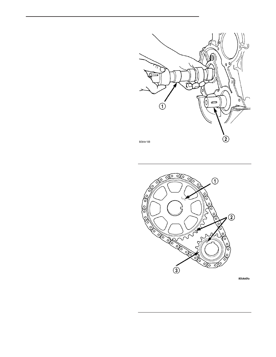
(11) Rotate the crankshaft until the crankshaft

sprocket timing mark is aligned on centerline with
the camshaft sprocket timing mark (Fig. 33).

(12) Remove the timing chain and sprockets (Refer

to 9 - ENGINE/VALVE TIMING/TIMING BELT/
CHAIN AND SPROCKETS - REMOVAL).

(13) Remove the front bumper and/or grille, as

required.

(14) Remove the two thrust plate retaining screws,

thrust plate and camshaft (Fig. 32).

Fig. 32 Camshaft Removal

1 - CAMSHAFT
2 - CRANKSHAFT

Fig. 33 Crankshaft / Camshaft Sprocket Timing Mark

Alignment

1 - CAMSHAFT SPROCKET
2 - TIMING MARKS
3 - CRANKSHAFT SPROCKET

TJ

ENGINE 4.0L

9 - 99

CAMSHAFT & BEARINGS (IN BLOCK) (Continued)

INSTALLATION

INSTALLATION - CAMSHAFT BEARINGS

CAUTION: Make sure outside diameter of number 1
bearing is clean. Make sure that the bearing is
properly installed in the engine block, align the oil
hole in the bearing with the oil gallery in the bear-
ing bore. Failure to do so will cause inadequate oil
supply for the sprockets and timing chain.

(1) Using recommended special tool 8544 Cam-

shaft Bearing Remover/Installer, install new cam-
shaft bearings.

INSTALLATION - CAMSHAFT

(1) Lubricate the camshaft with Mopar

t Engine

Oil Supplement, or equivalent.

(2) Carefully install the camshaft to prevent dam-

age to the camshaft bearings.

(3) Position thrust plate and install retaining

screws. Tighten screws to 24 N·m (18 ft. lbs.).

(4) Lubricate the camshaft with Mopar

t engine oil

supplement, or equivalent.

(5) Install

the

camshaft

sprocket,

crankshaft

sprocket and timing chain (Refer to 9 - ENGINE/
VALVE

TIMING/TIMING

BELT/CHAIN

AND

SPROCKETS - INSTALLATION).

(6) Tighten the camshaft sprocket bolt and washer

to 68 N·m (50 ft. lbs.).

(7) To verify correct installation of the timing

chain, turn the crankshaft two full revolutions then
position the camshaft sprocket timing mark as shown
in (Fig. 34).

(8) Install the timing case cover with a replace-

ment oil seal (Fig. 35). (Refer to 9 - ENGINE/VALVE
TIMING/TIMING

BELT

/

CHAIN

COVER(S)

-

INSTALLATION).

(9) Install the vibration damper (Fig. 35) (Refer to

9

-

ENGINE/ENGINE

BLOCK/VIBRATION

DAMPER - INSTALLATION).

(10) Install the hydraulic valve tappets (Refer to 9

- ENGINE/ENGINE BLOCK/HYDRAULIC LIFTERS
(CAM IN BLOCK) - INSTALLATION).

(11) Install the cylinder head gasket with the

numbers facing up.

(12) Install

the

cylinder

head

(Refer

to

9

-

ENGINE/CYLINDER HEAD - INSTALLATION).

(13) Install the push rods.
(14) Install the rocker arms and pivot and bridge

assemblies (Refer to 9 - ENGINE/CYLINDER HEAD/
ROCKER ARM / ADJUSTER ASSY - INSTALLA-
TION).

(15) Install the engine cylinder head cover (Refer

to

9

-

ENGINE/CYLINDER

HEAD/CYLINDER

HEAD COVER(S) - INSTALLATION).

(16) Install the serpentine drive belt (Refer to 7 -

COOLING/ACCESSORY

DRIVE/DRIVE

BELTS

-

INSTALLATION).

Fig. 34 Crankshaft / Camshaft Chain Drive

Installation—Typical

1 - CAMSHAFT SPROCKET
2 - TIMING MARKS
3 - CRANKSHAFT SPROCKET

Fig. 35 Timing Case Cover Components

1 - TIMING CASE COVER
2 - OIL SLINGER
3 - CRANKSHAFT OIL SEAL
4 - VIBRATION DAMPER PULLEY

9 - 100

ENGINE 4.0L

TJ

CAMSHAFT & BEARINGS (IN BLOCK) (Continued)

NOTE: During installation, lubricate the hydraulic
valve

tappets

and

all

valve

components

with

Mopar

T

Engine Oil Supplement, or equivalent. The

Mopar

T

Engine Oil Supplement, or equivalent must

remain with the engine oil for at least 1609 km
(1,000 miles). The oil supplement need not be
drained until the next scheduled oil change.

(17) Install the radiator (Refer to 7 - COOLING/

ENGINE/RADIATOR - INSTALLATION).

(18) Check the ignition timing and adjust as nec-

essary.

(19) Install the grille and bumper, if removed.
(20) Connect negative cable to battery.

CONNECTING ROD BEARINGS

STANDARD PROCEDURE - FITTING
CONNECTING ROD BEARINGS

Inspect the connecting rod bearings for scoring and

bent alignment tabs (Fig. 36) (Fig. 37). Check the
bearings for normal wear patterns, scoring, grooving,
fatigue and pitting (Fig. 38). Replace any bearing
that shows abnormal wear.

Inspect the connecting rod journals for signs of

scoring, nicks and burrs.

Misaligned or bent connecting rods can cause

abnormal wear on pistons, piston rings, cylinder
walls, connecting rod bearings and crankshaft con-
necting rod journals. If wear patterns or damage to
any of these components indicate the probability of a

misaligned connecting rod, inspect it for correct rod
alignment. Replace misaligned, bent or twisted con-
necting rods.

BEARING-TO-JOURNAL CLEARANCE

(1) Wipe the oil from the connecting rod journal.
(2) Use short rubber hose sections over rod bolts

during installation.

(3) Lubricate the upper bearing insert and install

in connecting rod.

(4) Use piston ring compressor to install the rod

and piston assemblies. The oil squirt holes in the
rods must face the camshaft. The arrow on the piston
crown should point to the front of the engine (Fig.
39). Verify that the oil squirt holes in the rods face
the camshaft and that the arrows on the pistons face
the front of the engine.

(5) Install the lower bearing insert in the bearing

cap. The lower insert must be dry. Place strip of Plas-
tigage across full width of the lower insert at the cen-
ter of bearing cap. Plastigage must not crumble in
use. If brittle, obtain fresh stock.

(6) Install bearing cap and connecting rod on the

journal and tighten nuts to 45 N·m (33 ft. lbs.)
torque. DO NOT rotate crankshaft. Plastigage will
smear, resulting in inaccurate indication.

Fig. 36 Connecting Rod Bearing Inspection

1 - UPPER BEARING HALF
2 - MATING EDGES
3 - GROOVES CAUSED BY ROD BOLTS SCRATCHING JOURNAL
DURING INSTALLATION
4 - WEAR PATTERN - ALWAYS GREATER ON UPPER BEARING
5 - LOWER BEARING HALF

Fig. 37 Locking Tab Inspection

1 - ABNORMAL CONTACT AREA CAUSED BY LOCKING TABS
NOT FULLY SEATED OR BEING BENT

Fig. 38 Scoring Caused by Insufficient Lubrication

or Damaged Crankshaft Journal

TJ

ENGINE 4.0L

9 - 101

CAMSHAFT & BEARINGS (IN BLOCK) (Continued)

(7) Remove the bearing cap and determine amount

of bearing-to- journal clearance by measuring the
width of compressed Plastigage (Fig. 40). Plastigage
should indicate the same clearance across the
entire width of the insert. If the clearance var-
ies, it may be caused by either a tapered jour-
nal, bent connecting rod or foreign material
trapped between the insert and cap or rod.

(8) If the correct clearance is indicated, replace-

ment of the bearing inserts is not necessary. Remove
the Plastigage from crankshaft journal and bearing
insert. Proceed with installation.

(9) If

bearing-to-journal

clearance

exceeds

the

specification, install a pair of 0.0254 mm (0.001 inch)
undersize bearing inserts. All the odd size inserts
must be on the bottom. The sizes of the service

replacement bearing inserts are stamped on the
backs of the inserts. Measure the clearance as
described in the previous steps.

(10) The clearance is measured with a pair of

0.0254 mm (0.001 inch) undersize bearing inserts
installed. This will determine if two 0.0254 mm
(0.001 inch) undersize inserts or another combination
is needed to provide the correct clearance. Refer to
CONNECTING ROD BEARING FITTING CHART.

CONNECTING ROD BEARING FITTING CHART

CRANKSHAFT JOURNAL

CORRESPONDING ROD BEARING INSERT

Color Code

Diameter

Upper Insert Size

Lower Insert Size

Yellow

53.2257 - 53.2079 mm

Yellow - Standard

Yellow - Standard

(2.0955 - 2.0948 in.)

Orange

53.2079 - 53.1901 mm

Yellow - Standard

Blue - Undersize

(2.0948 - 2.0941 in.)

0.0178 mm (0.0007 in.)

0.025 mm (0.001 in.)

Undersize

Blue

53.1901 - 53.1724 mm

Blue - Undersize

Blue - Undersize

(2.0941 - 2.0934 in.)

0.0356 mm (0.0014 in.)

0.025 mm (0.001 in.)

0.025 mm (0.001 in.)

Undersize

Red

52.9717 - 52.9539 mm

Red - Undersize

Red - Undersize

(2.0855 - 2.0848 in.)

0.254 mm (0.010 in.)

0.254 mm (0.010 in.)

0.254 mm (0.010 in.)

Undersize

Fig. 39 Rod and Piston Assembly Installation

Fig. 40 Measuring Bearing Clearance with

Plastigage

1 - PLASTIGAGE SCALE
2 - COMPRESSED PLASTIGAGE

9 - 102

ENGINE 4.0L

TJ

CONNECTING ROD BEARINGS (Continued)


Content   ..  444  445  446  447   ..