Jeep Wrangler TJ. Manual - part 443


  Index      Jeep     Jeep Wrangler TJ - service repair manual 2005 year


Search            


Content   ..  441  442  443  444   ..


Jeep Wrangler TJ. Manual - part 443


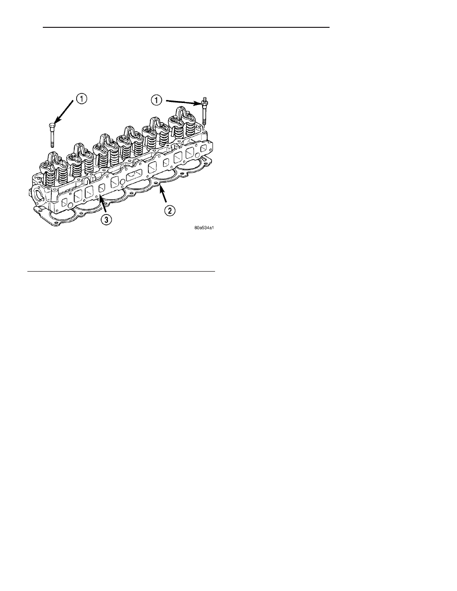
The cylinder head uses dual quench-type design

combustion chambers which cause turbulence in the
cylinders allowing faster burning of the air/fuel mix-
ture, resulting in better fuel economy (Fig. 9).

DIAGNOSIS AND TESTING - ENGINE CYLINDER
HEAD GASKET FAILURE

A leaking engine cylinder head gasket usually

results in loss of power, loss of coolant and engine
misfiring.

An engine cylinder head gasket leak can be located

between adjacent cylinders or between a cylinder and
the adjacent water jacket.

• An engine cylinder head gasket leaking between

adjacent cylinders is indicated by a loss of power
and/or engine misfire.

• An engine cylinder head gasket leaking between

a cylinder and an adjacent water jacket is indicated
by coolant foaming or overheating and loss of coolant.

CYLINDER-TO-CYLINDER LEAKAGE TEST

To determine if an engine cylinder head gasket is

leaking between adjacent cylinders; follow the proce-
dures outlined . An engine cylinder head gasket leak-
ing

between

adjacent

cylinders

will

result

in

approximately a 50-70% reduction in compression
pressure.

CYLINDER-TO-WATER JACKET LEAKAGE TEST

WARNING: USE EXTREME CAUTION WHEN THE
ENGINE IS OPERATING. DO NOT STAND IN A
DIRECT LINE WITH THE FAN. DO NOT PUT YOUR
HANDS NEAR THE PULLEYS, BELTS OR THE FAN.
DO NOT WEAR LOOSE CLOTHING.

Remove the radiator cap.
Start the engine and allow it to warm up until the

engine thermostat opens.

If a large combustion/compression pressure leak

exists, bubbles will be visible in the coolant.

If bubbles are not visible, install a radiator pres-

sure tester and pressurize the coolant system.

If a cylinder is leaking combustion pressure into

the water jacket, the tester pointer will pulsate with
every combustion stroke of the cylinder.

REMOVAL

NOTE: This procedure can be done with the engine
in or out of the vehicle.

(1) Disconnect the battery negative cable.

WARNING:

DO

NOT

REMOVE

THE

CYLINDER

BLOCK DRAIN PLUGS OR LOOSEN THE RADIATOR
DRAIN COCK WITH THE SYSTEM HOT AND PRES-
SURIZED BECAUSE SERIOUS BURNS FROM THE
COOLANT CAN OCCUR.

(2) Drain the coolant (Refer to 7 - COOLING -

STANDARD PROCEDURE) and disconnect the hoses
at the engine thermostat housing and the water
pump inlet. DO NOT waste reusable coolant. If the
solution is clean and is being drained only to service
the engine or cooling system, drain the coolant into a
clean container for reuse.

(3) Remove the air cleaner assembly.
(4) Remove the cylinder head cover (Refer to 9 -

ENGINE/CYLINDER

HEAD/CYLINDER

HEAD

COVER(S) - REMOVAL).

(5) Remove the capscrews, bridge and pivot assem-

blies and rocker arms (Refer to 9 - ENGINE/CYLIN-
DER HEAD/ROCKER ARM / ADJUSTER ASSY -
REMOVAL).

(6) Remove the push rods.Retain the push rods,

bridges, pivots and rocker arms in the same
order as removed.

(7) Remove the accessory drive belt (Refer to 7 -

COOLING/ACCESSORY

DRIVE/DRIVE

BELTS

-

REMOVAL).

(8) Remove the A/C compressor mounting bolts

and secure the compressor to the side.

(9) Remove the power steering pump and bracket

from the intake manifold and water pump. Set the
pump and bracket aside. DO NOT disconnect the
hoses.

(10) Perform the Fuel System Pressure Release

procedure (Refer to 14 - FUEL SYSTEM/FUEL
DELIVERY - STANDARD PROCEDURE).

(11) Disconnect the fuel supply line at the fuel rail.

Fig. 9 Cylinder Head 4.0L Engine

1 - CYLINDER HEAD BOLTS
2 - CYLINDER HEAD GASKET
3 - CYLINDER HEAD

TJ

ENGINE 4.0L

9 - 87

CYLINDER HEAD (Continued)

(12) Remove the intake and exhaust manifolds

from the engine cylinder head (Refer to 9 - ENGINE/
MANIFOLDS/INTAKE MANIFOLD - REMOVAL).

(13) Disconnect the coil rail electrical connectors

and remove the coil rail (Refer to 8 - ELECTRICAL/
IGNITION CONTROL/COIL RAIL - REMOVAL).

(14) Remove spark plugs (Refer to 8 - ELECTRI-

CAL/IGNITION

CONTROL/SPARK

PLUG

-

REMOVAL).

(15) Disconnect the temperature sending unit wire

connector.

(16) Remove the engine cylinder head bolts. Bolt

No.14 cannot be removed until the head is moved for-
ward (Fig. 10). Pull bolt No.14 out as far as it will go
and then suspend the bolt in this position (tape
around the bolt).

(17) Remove the engine cylinder head and gasket

(Fig. 10).

(18) If this was the first time the bolts were

removed, put a paint dab on the top of the bolt. If the
bolts have a paint dab on the top of the bolt or it
isn’t known if they were used before, discard the
bolts.

(19) Stuff clean lint free shop towels into the cyl-

inder bores.

NOTE: If the valves, springs, or seals are to be
inspected/replaced at this time, refer to Valves and
Valve Springs in this section for proper inspection
procedures.

CLEANING

Thoroughly clean the engine cylinder head and cyl-

inder block mating surfaces. Clean the intake and
engine exhaust manifold and engine cylinder head

mating surfaces. Remove all gasket material and car-
bon.

Check to ensure that no coolant or foreign material

has fallen into the tappet bore area.

Remove the carbon deposits from the combustion

chambers and top of the pistons.

INSPECTION

Use a straightedge and feeler gauge to check the

flatness of the engine cylinder head and block mating
surfaces.

INSTALLATION

NOTE: This procedure can be done with the engine
in or out of the vehicle.

The engine cylinder head gasket is a composition

gasket. The gasket is to be installed DRY. DO NOT
use a gasket sealing compound on the gasket.

If the engine cylinder head is to be replaced and

the original valves used, measure the valve stem
diameter. Only standard size valves can be used with
a service replacement engine cylinder head unless
the replacement head valve stem guide bores are
reamed

to

accommodate

oversize

valve

stems.

Remove all carbon buildup and reface the valves.

(1) Remove the shop towels from the cylinder

bores. Coat the bores with clean engine oil.

(2) Position the engine cylinder head gasket (with

the numbers facing up) using the alignment dowels
in the cylinder block, to position the gasket.

CAUTION: Engine cylinder head bolts should be
reused only once. Replace the head bolts if they
were used before or if they have a paint dab on the
top of the bolt.

(3) With bolt No.14 held in place (tape around

bolt), install the engine cylinder head over the same
dowels used to locate the gasket. Remove the tape
from bolt No.14.

(4) Coat the threads of stud bolt No.11 with Loc-

tite 592 sealant, or equivalent.

(5) Tighten the engine cylinder head bolts in

sequence according to the following procedure (Fig.
11).

CAUTION: During the final tightening sequence,
bolt No.11 will be tightened to a lower torque than
the rest of the bolts. DO NOT overtighten bolt
No.11.

(a) Tighten all bolts in sequence (1 through 14)

to 30 N·m (22 ft. lbs.) torque.

(b) Tighten all bolts in sequence (1 through 14)

to 61 N·m (45 ft. lbs.) torque.

Fig. 10 Engine Cylinder

1 - CYLINDER HEAD BOLTS
2 - CYLINDER HEAD GASKET
3 - CYLINDER HEAD

9 - 88

ENGINE 4.0L

TJ

CYLINDER HEAD (Continued)

(c) Check all bolts to verify they are set to 61

N·m (45 ft. lbs.) torque.

(d) Tighten bolts in sequence:

• Bolts 1 through 10 to 149 N·m (110 ft. lbs.)

torque.

• Bolt 11 to 135 N·m (100 ft. lbs.) torque.

• Bolts 12 through 14 to 149 N·m (110 ft. lbs.)

torque.

(e) Check all bolts in sequence to verify the cor-

rect torque.

(f) If not already done, clean and mark each bolt

with a dab of paint after tightening. Should you
encounter bolts which were painted in an earlier
service operation, replace them.

(6) Install the spark plugs (Refer to 8 - ELECTRI-

CAL/IGNITION CONTROL/SPARK PLUG - INSTAL-
LATION).

(7) Connect the temperature sending unit wire

connector.

(8) Install the ignition coil rail and coil rail electri-

cal connectors (Refer to 8 - ELECTRICAL/IGNITION
CONTROL/COIL RAIL - INSTALLATION).

(9) Install the intake and exhaust manifolds (Refer

to 9 - ENGINE/MANIFOLDS/INTAKE MANIFOLD -
INSTALLATION).

(10) Install the fuel line and the vacuum advance

hose.

(11) Attach the power steering pump and bracket.
(12) Install the push rods, rocker arms, pivots and

bridges in the order they were removed (Refer to 9 -
ENGINE/CYLINDER

HEAD/ROCKER

ARM

/

ADJUSTER ASSY - INSTALLATION).

(13) Install the engine cylinder head cover (Refer

to

9

-

ENGINE/CYLINDER

HEAD/CYLINDER

HEAD COVER(S) - INSTALLATION).

(14) Attach the air conditioner compressor mount-

ing bracket to the engine cylinder head and block.
Tighten the bolts to 40 N·m (30 ft. lbs.) torque.

(15) Attach the air conditioning compressor to the

bracket. Tighten the bolts to 27 N·m (20 ft. lbs.)
torque.

CAUTION: The serpentine drive belt must be routed
correctly. Incorrect routing can cause the water
pump to turn in the opposite direction causing the
engine to overheat.

(16) Install the serpentine drive belt (Refer to 7 -

COOLING/ACCESSORY

DRIVE/DRIVE

BELTS

-

INSTALLATION).

(17) Install the air cleaner and ducting.
(18) Connect the hoses to the engine thermostat

housing and fill the cooling system to the specified
level (Refer to 7 - COOLING - STANDARD PROCE-
DURE).

(19) The automatic transmission throttle linkage

and cable must be adjusted after completing the
engine cylinder head installation (Refer to 21 -
TRANSMISSION/TRANSAXLE/AUTOMATIC

-

30RH/THROTTLE

VALVE

CABLE

-

ADJUST-

MENTS) or (Refer to 21 - TRANSMISSION/TRANS-
AXLE/AUTOMATIC

-

32RH/THROTTLE

VALVE

CABLE - ADJUSTMENTS).

(20) Install the temperature sending unit and con-

nect the wire connector.

(21) If equipped with air conditioning, install A/C

compressor (Refer to 24 - HEATING & AIR CONDI-
TIONING/PLUMBING/A/C

COMPRESSOR

-

INSTALLATION) and charge A/C system (Refer to 24
- HEATING & AIR CONDITIONING/PLUMBING -
STANDARD PROCEDURE).

(22) Connect negative cable to battery.

WARNING: USE EXTREME CAUTION WHEN THE
ENGINE IS OPERATING. DO NOT STAND IN DIRECT
LINE WITH THE FAN. DO NOT PUT HANDS NEAR
THE PULLEYS, BELTS OR FAN. DO NOT WEAR
LOOSE CLOTHING.

(23) Operate the engine with the radiator cap off.

Inspect for leaks and continue operating the engine
until the engine thermostat opens. Add coolant, if
required.

Fig. 11 Engine Cylinder Head Bolt Tightening

Sequence

TJ

ENGINE 4.0L

9 - 89

CYLINDER HEAD (Continued)

CYLINDER HEAD COVER(S)

DESCRIPTION

The cylinder head cover (Fig. 12) is made of

stamped steel and incorporates the Crankcase Venti-
lation (CCV) Hoses and the oil fill opening.

REMOVAL

The cylinder head cover is isolated from the cylin-

der head via grommets and a reusable molded rubber
gasket. The grommet and limiter are retained in the
cylinder head cover.

(1) Disconnect negative cable from battery.
(2) Disconnect the Crankcase Ventilation (CCV)

vacuum hose from engine cylinder head cover.

(3) Disconnect the fresh air inlet hose from the

engine cylinder head cover.

(4) Disconnect the accelerator, transmission, and

speed (if equipped) control cables from the throttle
body (Fig. 13).

(5) Remove the three bolts that fasten the control

cable bracket to the intake manifold.

(6) Remove control cables from cylinder head cover

clip.

(7) Position control cables and bracket away from

cylinder head cover secure with tie straps.

NOTE: The wiring harness loom on the left hand
side of the engine must be disconnected and
moved over to the right hand side of the engine to
gain clearance for cylinder head cover removal.

(8) Disconnect the left hand side of the wiring har-

ness loom from all components.

(9) Remove fasteners from plastic wiring loom

trough on rear of cylinder head cover.

NOTE: Before trying to move the Left side of the
harness to the right side, remove the tie strap from

the harness on the right side, just below the cover,
near the coil pack area, if equipped.

(10) Move the left hand side harness loom and the

plastic trough to the right side.

(11) Remove

the

engine

cylinder

head

cover

mounting bolts.

(12) Remove the engine cylinder head cover and

gasket.

CLEANING

Remove any original sealer from the cover sealing

surface of the engine cylinder head and clean the
surface using a fabric cleaner.

Remove all residue from the sealing surface using

a clean, dry cloth.

INSPECTION

Inspect the engine cylinder head cover for cracks.

Replace the cover, if cracked.

The original dark grey gasket material should

NOT be removed. If sections of the gasket material
are missing or are compressed, replace the engine
cylinder head cover. However, sections with minor
damage such as small cracks, cuts or chips may be
repaired with a hand held applicator. The new mate-
rial must be smoothed over to maintain gasket
height. Allow the gasket material to cure prior to
engine cylinder head cover installation.

INSTALLATION

The cylinder head cover is isolated from the cylin-

der head via grommets and a reusable molded rubber
gasket. The grommet and limiter are retained in the
cylinder head cover.

Fig. 12 Cylinder Head Cover

Fig. 13 Engine Cylinder Head Cover

1 - TRANS CONTROL CABLE
2 - ACCELERATOR CABLE
3 - CONTROL CABLE BRACKET
4 - CYLINDER HEAD COVER

9 - 90

ENGINE 4.0L

TJ


Content   ..  441  442  443  444   ..