Jeep Wrangler TJ. Manual - part 341


  Index      Jeep     Jeep Wrangler TJ - service repair manual 2005 year


Search            


Content   ..  339  340  341  342   ..


Jeep Wrangler TJ. Manual - part 341


adjusted or repaired. If faulty, worn, or damaged the
entire wiper blade unit must be replaced.

OPERATION

The rear wiper blade is moved back and forth

across the glass by the wiper arm when the rear
wiper system is in operation. The wiper blade super-
structure is the flexible frame that grips the wiper
blade element and evenly distributes the force of the
spring-loaded wiper arm along the length of the ele-
ment. The combination of the wiper arm force and
the flexibility of the superstructure makes the ele-
ment conform to and maintain proper contact with
the liftglass, even as the blade is moved over the var-
ied curvature found across the glass surface.

The wiper element flexor provides the claws of the

blade superstructure with a rigid, yet flexible compo-
nent on the element which can be gripped. The rub-
ber element is designed to be stiff enough to
maintain an even cleaning edge as it is drawn across
the glass, but resilient enough to conform to the
glass surface and flip from one cleaning edge to the
other each time the wiper blade changes directions.

REMOVAL

NOTE: The notched end of the wiper element flexor
should always be oriented towards the end of the
wiper blade that is nearest to the rear wiper motor
output shaft.

(1) Lift the rear wiper arm to raise the wiper blade

and element off of the liftglass.

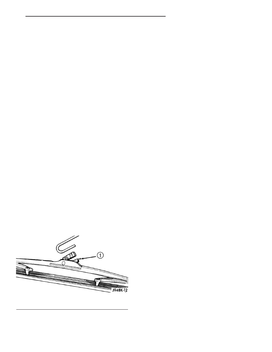
(2) To remove the wiper blade from the wiper arm,

push the pivot block latch release tab under the tip
of the arm and slide the blade away from the tip
towards the rear wiper motor output shaft end of the
arm (Fig. 17).

(3) Slide the rear wiper blade away from the tip of

the arm towards the pivot end of the arm far enough
to disengage the pivot block from the hook formation
on the end of the arm.

(4) Extract the hook formation on the tip of the

wiper arm from the opening in the wiper blade
superstructure ahead of the wiper blade pivot block/
latch unit.

CAUTION: Do not allow the wiper arm to spring
back against the liftglass without the wiper blade in
place or the glass may be damaged.

(5) Gently lower the wiper arm tip onto the glass.

INSTALLATION

NOTE: The notched end of the wiper element flexor
should always be oriented towards the end of the
wiper blade that is nearest to the rear wiper motor
output shaft.

(1) Lift the rear wiper arm off of the liftglass.
(2) Position the rear wiper blade near the hook for-

mation on the tip of the arm with the notched end of
the wiper element flexor oriented towards the end of
the wiper arm that is nearest to the rear wiper motor
output shaft.

(3) Insert the hook formation on the tip of the

wiper arm through the opening in the wiper blade
superstructure ahead of the wiper blade pivot block/
latch unit far enough to engage the pivot block with
the hook (Fig. 17).

(4) Slide the wiper blade pivot block/latch up into

the hook formation on the tip of the wiper arm until
the latch release tab snaps into its locked position.

(5) Gently lower the wiper blade onto the liftglass.

REAR WIPER MOTOR

DESCRIPTION

The rear wiper motor is concealed behind a molded

plastic trim cover on the inside of the liftglass near
the right liftglass hinge at the top of the glass. A
large blackout area of the liftglass conceals the unit
from the exterior of the vehicle. The end of the motor
output shaft that protrudes through a large rubber
grommet in the liftglass to drive the rear wiper arm
and blade is the only visible component of the rear
wiper motor (Fig. 18). A large flat washer and a nut
secure and seal the motor output shaft to the outside
of the liftglass, while a rubber insulator in a slot on
the outboard upper corner of the motor bracket is
secured by a stud and nut to the inside of the lift-
glass near the right liftglass hinge. The connector of
a short pigtail harness is secured to a tab on the
back of the motor bracket, and connects the rear
wiper motor to the vehicle electrical system through
a dedicated take out and connector of the hardtop

Fig. 17 Wiper Blade Remove/Install - Typical

1 - RELEASE TAB

TJ

REAR WIPERS/WASHERS

8R - 37

REAR WIPER BLADE (Continued)

wire harness. The rear wiper motor consists of the
following major components:

• Bracket - The rear wiper motor bracket consists

of a stamped steel mounting plate that is secured
with screws to the wiper motor and transmission. A
rubber insulator in a slot on the upper outboard cor-
ner of the bracket is secured by a nut and washer to
a stud on the inside surface of the liftglass. An inte-
gral tab on the back of the bracket supports the
wiper motor pigtail wire connector.

• Motor - The single-speed permanent magnet

rear wiper motor is secured with screws to the rear
wiper motor bracket. The wiper motor includes an
integral transmission, a motor output shaft, a diode,
and the rear wiper motor park switch.

The rear wiper motor cannot be adjusted or

repaired. If any component of the motor is faulty or
damaged, the entire rear wiper motor unit must be
replaced. The motor output shaft grommet, washer
and nut are available for individual service replace-
ment.

OPERATION

The rear wiper motor operation is controlled by the

vehicle operator through battery current inputs
received by the rear wiper motor from the rear wiper
and washer switch on the instrument panel, and the
rear wiper motor park switch, which control current
flow to the wiper motor brushes. An internal diode
protects the motor from feedback through the park
switch when the switch is closed to the fused ignition
switch output (run) circuit. An internal circuit
breaker protects the motor from overloads.

The park switch is a single pole, single throw,

momentary switch within the wiper motor that is
mechanically actuated by the wiper motor transmis-

sion components. The park switch alternately closes
the wiper motor brush to the rear wiper and washer
switch output or to a fused ignition switch output
(run) circuit, depending upon the position of the
wiper on the glass. This feature allows the motor to
complete its current wipe cycle after the wiper sys-
tem has been turned Off, and to park the wiper blade
in the uppermost portion of the wipe pattern.

The wiper motor transmission converts the rotary

output of the wiper motor to the back and forth wip-
ing motion of the rear wiper arm and blade on the
liftglass. The rear wiper motor may be diagnosed
using conventional diagnostic tools and methods.

REMOVAL

(1) Disconnect and isolate the battery negative

cable.

(2) Remove the rear wiper arm from the rear

wiper motor output shaft. (Refer to 8 - ELECTRI-
CAL/REAR WIPERS/WASHERS/REAR WIPER ARM
- REMOVAL).

(3) Remove the nut that secures the threaded

sleeve of the rear wiper motor output shaft to the
outside of the liftglass (Fig. 19).

(4) Remove the washer from the rear wiper motor

output shaft sleeve.

(5) Remove the trim cover from the rear wiper

motor on the inside of the liftglass. (Refer to 8 -
ELECTRICAL/REAR

WIPERS/WASHERS/REAR

WIPER MOTOR TRIM COVER - REMOVAL).

Fig. 18 Rear Wiper Motor

1 - OUTPUT SHAFT
2 - TRANSMISSION
3 - PIGTAIL CONNECTOR (ON BACK)
4 - INSULATOR
5 - BRACKET
6 - MOTOR
7 - PIGTAIL WIRES

Fig. 19 Rear Wiper Motor Output Shaft

1 - WASHER
2 - NUT
3 - GROMMET
4 - STUD
5 - LIFTGLASS
6 - REAR WASHER NOZZLE
7 - REAR WIPER MOTOR OUTPUT SHAFT

8R - 38

REAR WIPERS/WASHERS

TJ

REAR WIPER MOTOR (Continued)

(6) Disconnect the hardtop wire harness connector

for the rear wiper motor from the motor pigtail wire
connector.

(7) Remove the nut and washer that secures the

rear wiper motor bracket insulator to the stud on the
liftglass (Fig. 20).

(8) Remove the washer from the stud that secures

the rear wiper motor bracket insulator to the lift-
glass.

(9) From the inside of the liftglass, gently pull the

rear wiper motor away from the liftglass until the
output shaft clears the rubber grommet in the lift-
glass output shaft hole.

(10) Remove the rear wiper motor and mounting

bracket from the liftglass as a unit.

(11) Remove the rubber grommet from the outside

of the liftglass output shaft hole.

INSTALLATION

(1) Install the rubber grommet from the outside of

the liftglass output shaft hole. Be certain that the
alignment arrow molded into the outer flange of the
grommet is aligned with the arrowhead imprinted on
the glass below the output shaft hole.

(2) Position the rear wiper motor to the inside of

the liftglass with the output shaft inserted through
the rubber grommet and the mounting bracket insu-
lator installed over the stud on the inside of the lift-
glass (Fig. 20).

(3) Reinstall the washer onto the stud that secures

the rear wiper motor bracket insulator to the lift-
glass.

(4) Install and tighten the nut and washer that

secures the rear wiper motor bracket insulator to the
stud on the liftglass. Tighten the nut to 6 N·m (54 in.
lbs.).

(5) From the outside of the liftglass, reinstall the

washer over the rear wiper motor output shaft sleeve
(Fig. 19).

(6) Install and tighten the nut that secures the

threaded sleeve of the rear wiper motor output shaft
to the outside of the liftglass. Tighten the nut to 5
N·m (44 in. lbs.).

(7) Reconnect the hardtop wire harness connector

for the rear wiper motor to the motor pigtail wire
connector.

(8) Reinstall the trim cover over the rear wiper

motor on the inside of the liftglass. (Refer to 8 -
ELECTRICAL/REAR

WIPERS/WASHERS/REAR

WIPER MOTOR TRIM COVER - INSTALLATION).

(9) Reinstall the rear wiper arm onto the rear

wiper motor output shaft. (Refer to 8 - ELECTRI-
CAL/REAR WIPERS/WASHERS/REAR WIPER ARM
- INSTALLATION).

(10) Reconnect the battery negative cable.

REAR WIPER MOTOR TRIM
COVER

REMOVAL

(1) From the inside of the liftglass, remove the

three screws that secure the rear wiper motor trim
cover to the motor mounting bracket (Fig. 21).

(2) Remove the trim cover from the rear wiper

motor mounting bracket.

Fig. 20 Rear Wiper Motor Bracket

1 - BRACKET
2 - INSULATOR
3 - RIGHT LIFTGLASS HINGE
4 - LIFTGLASS
5 - WASHER
6 - STUD
7 - NUT

Fig. 21 Rear Wiper Motor Trim Cover Remove/Install

1 - SCREW (3)
2 - TRIM COVER
3 - REAR WIPER MOTOR
4 - LIFTGLASS

TJ

REAR WIPERS/WASHERS

8R - 39

REAR WIPER MOTOR (Continued)

INSTALLATION

(1) From the inside of the liftglass, position the

trim cover onto the rear wiper motor mounting
bracket (Fig. 21).

(2) Install and tighten the three screws that secure

the trim cover to the rear wiper motor mounting
bracket. Tighten the screws to 1 N·m (10 in. lbs.).

REAR WIPER/WASHER
SWITCH

DESCRIPTION

The rear wiper and washer switch is located in the

accessory switch bezel near the bottom of the instru-
ment panel center stack area on the instrument
panel (Fig. 22). Only the single switch toggle button
is visible through the opening of the accessory switch
bezel (Fig. 23). The remainder of the switch is con-
cealed behind the accessory switch bezel within the
instrument panel. The single two-function switch
housing and switch toggle button are molded from
black plastic. The switch toggle button is clearly
identified by a white graphic of the International
Control and Display Symbol icon for “Rear Wiper and
Washer,” making it clearly visible in daylight. When
illuminated from behind by an integral panel lamps
dimmer controlled illumination lamp with the exte-
rior lamps turned On, the white graphic appears
blue-green.

The rear wiper and washer switch is secured by a

snap fit within a dedicated receptacle molded into
the back of the accessory switch bezel. A single six
pin connector receptacle is molded into the back of
the switch housing. A dedicated take out and connec-
tor of the instrument panel wire harness connects
the switch to the vehicle electrical system. The rear
wiper and washer switch contains switches and cir-
cuitry to control both the rear wiper and the rear
washer functions. The rear wiper and washer switch
cannot be repaired and, if faulty or damaged, the
entire switch unit must be replaced. The incandes-
cent switch illumination bulb and bulb holder unit is
available for individual service replacement.

OPERATION

The rear wiper and washer switch uses convention-

ally switched outputs to control the functions and
features of the rear wiper and washer system. The
switch receives battery current on a fused ignition
switch output (run) circuit from a fuse in the Power
Distribution Center (PDC) through the rear wiper
and washer system fuse in the fuse block whenever
the ignition switch is in the On position. The switch
receives a path to ground at all times through a
through a take out of the instrument panel wire har-
ness with an eyelet terminal connector that is
secured by a ground screw to the support structure
near the driver side end of the instrument panel.

The rear wiper and washer switch features detents

in the Off and Wipe positions, and a momentary
Wash position. When the switch toggle button is in
the Off position it provides a ground path to the park
switch within the rear wiper motor. The park switch
uses this ground path to operate the rear wiper
motor until the wiper blade is in its parked position,

Fig. 22 Accessory Switch Bezel

1 - ACCESSORY SWITCH BEZEL
2 - REAR WINDOW DEFOGGER SWITCH (HARDTOP ONLY)
3 - REAR WIPER/WASHER SWITCH (HARDTOP ONLY)
4 - OVERDRIVE-OFF SWITCH (AUTOMATIC TRANSMISSION
ONLY)
5 - AXLE LOCK SWITCH (OFF ROAD PACKAGE ONLY)
6 - PASSENGER AIRBAG ON/OFF SWITCH (WITHOUT REAR
SEAT ONLY)
7 - ACCESSORY POWER OUTLET
8 - CIGAR LIGHTER

Fig. 23 Rear Wiper/Washer Switch

1 - CONNECTOR RECEPTACLE
2 - HOUSING
3 - TOGGLE BUTTON

8R - 40

REAR WIPERS/WASHERS

TJ

REAR WIPER MOTOR TRIM COVER (Continued)


Content   ..  339  340  341  342   ..