Jeep Wrangler TJ. Manual - part 221
(35) Verify differential case and ring gear runout
by measuring ring to pinion gear backlash at eight
locations around the ring gear. Readings should not
vary more than 0.05 mm (0.002 in.). If readings vary
more than specified, the ring gear or the differential
case is defective.
After the proper backlash is achieved, perform
Gear Contact Pattern Analysis procedure.
GEAR CONTACT PATTERN
The ring gear and pinion teeth contact patterns
will show if the pinion depth is correct in the hous-
ing. It will also show if the ring gear backlash has
been adjusted correctly. The backlash can be adjusted
within specifications to achieve desired tooth contact
patterns.
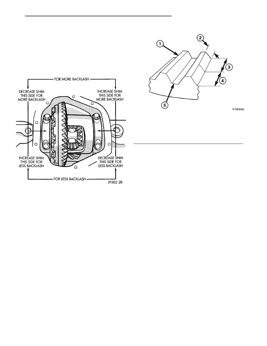
The TOP LAND of the gear tooth is the top surface
of the tooth. The PROFILE of the gear tooth is the
depth of the tooth. The TOE of the gear is the por-
tion of the tooth surface at the end towards the cen-
ter. The HEEL of the gear is the portion of the tooth
at the outer-end. The ROOT of the gear tooth is the
lowest portion of the tooth (Fig. 25).
NOTE: If the PROFILE across the tooth is the same
it is a 3 Axis cut gear. If the PROFILE across the
tooth is tapered it is a 2 Axis cut gear.
(1) Apply a thin coat of hydrated ferric oxide or
equivalent to the drive and coast side of the ring gear
teeth.
(2) Wrap, twist and hold a shop towel around the
pinion yoke to increase the turning resistance of the
pinion. This will provide a more distinct contact pat-
tern.
(3) With a boxed end wrench on the ring gear bolt,
rotate the differential case one complete revolution in
both directions while a load is being applied from
shop towel.
The areas on the ring gear teeth with the greatest
degree of contact against the pinion teeth will squee-
gee the compound to the areas with the least amount
of contact. Note and compare patterns on the ring
gear teeth to Gear Tooth Contact Patterns chart (Fig.
26) and (Fig. 27) and adjust pinion depth and gear
backlash as necessary.
DIFFERENTIAL BEARING PRELOAD CHECK
The final check on the differential assembly before
installing the axles is torque to rotate pinion and dif-
ferential combined. This will verify the correct differ-
ential bearing preload.
Torque to rotate the differential and pinion should
be the torque to rotate the pinion plus 0.79-1.24 N·m
(7-11 in. lbs.).
Fig. 24 BACKLASH SHIM
Fig. 25 GEAR DESCRIPTION
1 - TOP LAND
2 - PROFILE
3 - TOE
4 - HEEL
5 - ROOT
TJ
FRONT AXLE - 216FBI
3 - 61
FRONT AXLE - 216FBI (Continued)