Jeep Liberty KJ. Manual - part 917
REMOVAL
CAUTION: Before removing the cylinder head cov-
er/intake manifold (2) the engine must rotated to
90° after TDC to assure proper alignment of the
engine timing components. Failure to do so could
result in valve and/or piston damage during reas-
sembly. (Refer to 9 - ENGINE/VALVE TIMING -
STANDARD PROCEDURE)
1. Disconnect negative battery cable.
2. Drain cooling system (Refer to 7 - COOLING/EN-
GINE/COOLANT - STANDARD PROCEDURE).
3. Remove cooling fan and fan drive viscous clutch
assembly (Refer to 7 - COOLING/ENGINE/FAN
DRIVE VISCOUS CLUTCH - REMOVAL).
4. Remove accessory drive belt (Refer to 7 - COOL-
ING/ACCESSORY
DRIVE/DRIVE
BELTS
-
REMOVAL).
5. Remove the vibration damper.
6. Remove cooling fan support (Refer to 7 - COOL-
ING/ENGINE/RADIATOR FAN - REMOVAL).
7. Remove the power steering pump pulley.
8. Rotate the crankshaft to 90 degrees ATDC (Refer to 9 - ENGINE/VALVE TIMING - STANDARD PROCEDURE).
9. Remove outer timing belt cover (Refer to 9 - ENGINE/VALVE TIMING/TIMING BELT / CHAIN COVER(S) -
REMOVAL).
10. Remove timing belt (Refer to 9 - ENGINE/VALVE TIMING/TIMING BELT/CHAIN AND SPROCKETS -
REMOVAL).
11. Remove inner timing belt cover (Refer to 9 - ENGINE/VALVE TIMING/TIMING BELT / CHAIN COVER(S) -
REMOVAL).
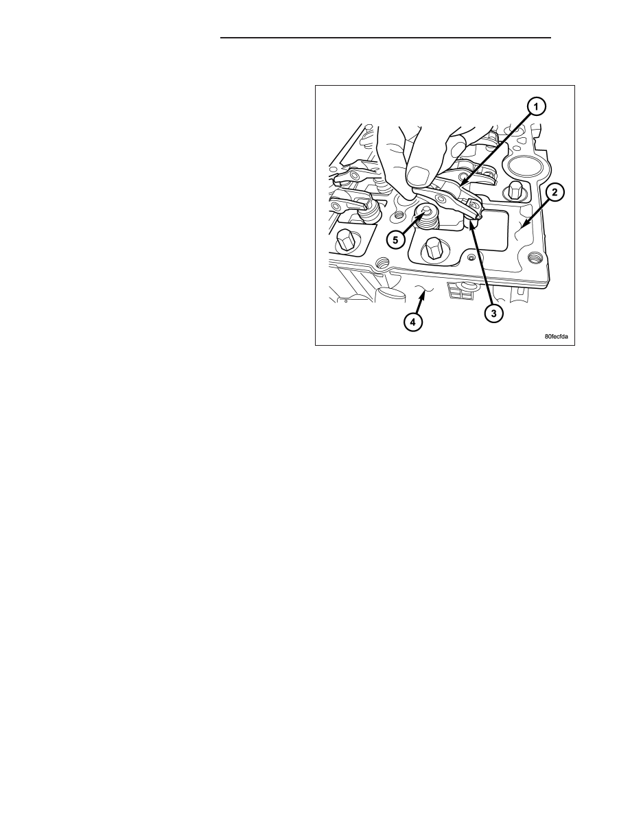
12. Remove cylinder head cover/intake manifold (2) (Refer to 9 - ENGINE/CYLINDER HEAD/CYLINDER HEAD
COVER(S) - REMOVAL).
NOTE: Lifters must be kept in order of removal and stored in the up right position.
13. Remove rocker arms (1) and lifters (3).
INSTALLATION
1. Clean and inspect gasket sealing surfaces.
2. Install new gasket on cylinder head.
3. Lubricate lifter ball end of lifter(s), valve(s), and rocker arm roller(s) with Mopar
T
Engine Oil Supplement or equiv-
lalent.
4. Connect rocker arm(s) to lifter and reposition on valve(s).
5. Install cylinder head cover/intake manifold (Refer to 9 - ENGINE/CYLINDER HEAD/CYLINDER HEAD COVER(S)
- INSTALLATION).
6. Install inner timing belt cover (Refer to 9 - ENGINE/VALVE TIMING/TIMING BELT / CHAIN COVER(S) - INSTAL-
LATION).
7. Install timing belt (Refer to 9 - ENGINE/VALVE TIMING/TIMING BELT/CHAIN AND SPROCKETS - INSTALLA-
TION).
8. Install outer timing belt cover (Refer to 9 - ENGINE/VALVE TIMING/TIMING BELT / CHAIN COVER(S) - INSTAL-
LATION).
9. Install vibration damper.
10. Install cooling fan support (Refer to 7 - COOLING/ENGINE/RADIATOR FAN - INSTALLATION).
9 - 1626
ENGINE - 2.8L DIESEL
KJ