Jeep Liberty KJ. Manual - part 902
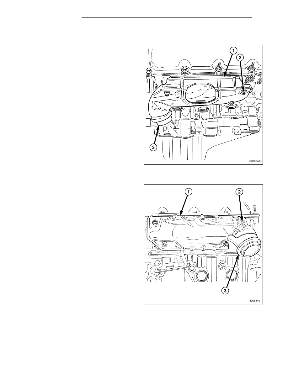
RIGHT EXHAUST MANIFOLD
1. Disconnect the negative cable from the battery.
2. Raise and support the vehicle.
3. Remove the bolts and nuts attaching the exhaust
pipe to the engine exhaust manifold.
4. Lower the vehicle.
5. Remove the exhaust heat shield (1).
6. Remove bolts, nuts and washers attaching mani-
fold to cylinder head.
7. Remove manifold and gasket from the cylinder
head.
LEFT EXHAUST MANIFOLD
1. Disconnect the negative cable from the battery.
2. Raise and support the vehicle.
3. Remove the bolts and nuts attaching the exhaust
pipe to the engine exhaust manifold.
4. Lower the vehicle.
5. Remove the exhaust heat shields (1).
6. Remove bolts, nuts and washers attaching mani-
fold to cylinder head.
7. Remove manifold and gasket from the cylinder
head.
INSTALLATION
RIGHT EXHAUST MANIFOLD
CAUTION: If the studs came out with the nuts when removing the engine exhaust manifold, install new
studs. Apply sealer on the coarse thread ends. Water leaks may develop at the studs if this precaution is
not taken.
9 - 1566
ENGINE - 3.7L
KJ