Jeep Liberty KJ. Manual - part 848


  Index      Jeep     Jeep Liberty KJ - service repair manual 2006 year


Search            


Content   ..  846  847  848  849   ..


Jeep Liberty KJ. Manual - part 848


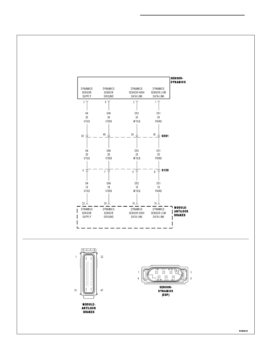
C1234–DRIVE TEST: SENSOR CLUSTER INSTALLATION

For a complete wiring diagram Refer to Section 8W.

5 - 152

BRAKES - ABS ELECTRICAL DIAGNOSTICS

KJ

When Monitored:
During the Drive Test.

Set Condition:
If the Anti-Lock Brakes Module detects implausible Dynamics Sensor data.

Possible Causes

WIRING HARNESS, TERMINAL, CONNECTOR DAMAGE

DYNAMICS SENSOR INSTALLATION

DYNAMICS SENSOR

ANTI-LOCK BRAKES MODULE

Diagnostic Test

1.

CHECK THE DYNAMICS SENSOR INSTALLATION

NOTE: Dynamics Sensor installation and mounting bolt torque is crucial for proper operation.
Turn the ignition off.

Check the Dynamics Sensor for damaged, modified, and bent mounting brackets.

Check the Dynamics Sensor mounting bolts for a loose or over tightened condition.

Were any problems found?

Yes

>> Repair as necessary.

Perform ABS VERIFICATION TEST - VER 1. (Refer to 5 - BRAKES - STANDARD PROCEDURE).

No

>> Go To 2

2.

INSPECT RELATED WIRING HARNESS, TERMINALS, & CONNECTORS

Visually inspect the related wiring harness. Look for any pinched, chafed, pierced, and partially broken wires.

Visually inspect the related wiring harness connectors. Look for broken, bent, pushed out, and corroded terminals.

Were any problems found?

Yes

>> Repair as necessary.

Perform ABS VERIFICATION TEST - VER 1. (Refer to 5 - BRAKES - STANDARD PROCEDURE).

No

>> Go To 3

3.

REPLACE DYNAMICS SENSOR & VERIFY IF DTC IS STILL ACTIVE

Replace the Dynamics Sensor in accordance with the Service Information.

Turn the ignition on.

With the scan tool, erase ABS DTCs.

Cycle the ignition switch.

WARNING: Ensure brake capability is available before road testing.

NOTE: The ECU Initialization process must include driving the vehicle into a 90° turn.
Using the scan tool, perform ECU Initialization (which includes Drive Test). Follow directions on the scan tool.

Park the vehicle.

With the scan tool, read ABS DTCs.

Does this DTC reset?

Yes

>> Replace the Anti-Lock Brakes Module in accordance with the Service Information.

Perform ABS VERIFICATION TEST - VER 1. (Refer to 5 - BRAKES - STANDARD PROCEDURE).

No

>> Perform ABS VERIFICATION TEST - VER 1. (Refer to 5 - BRAKES - STANDARD PROCEDURE).

KJ

BRAKES - ABS ELECTRICAL DIAGNOSTICS

5 - 153

C1238-DRIVE TEST: UNSUCCESSFUL

For a complete wiring diagram Refer to Section 8W.

When Monitored:
During the Drive Test.

Set Condition:
If the Anti-Lock Brakes Module detects a fault with the Steering Angle Sensor, the Pressure Sensor, or the
Dynamics Sensor.

Possible Causes

STEERING ANGLE SENSOR

PRESSURE SENSOR

DYNAMICS SENSOR

ANTI-LOCK BRAKES MODULE

Diagnostic Test

1.

DIAGNOSE & REPAIR ALL DTCs

Repair

Diagnose and repair all DTCs.

C1239–EMISSIONS ROLLS TEST ACTIVE

For a complete wiring diagram Refer to Section 8W.

Theory of Operation

This DTC sets when the Emissions Rolls Test is active. The functional effects are that the output signal for all wheel
speeds mimic the wheel with the highest wheel speed.

5 - 154

BRAKES - ABS ELECTRICAL DIAGNOSTICS

KJ

C123A–ESP SYSTEM SENSORS CALIBRATION

For a complete wiring diagram Refer to Section 8W.

When Monitored:
Once per ignition cycle.

Set Condition:
If the calculated checksum does not match the stored checksum.

Possible Causes

ANTI-LOCK BRAKES MODULE

Diagnostic Test

1.

REPLACE THE ANTI-LOCK BRAKES MODULE

Repair

Replace the Anti-Lock Brakes Module in accordance with the Service Information.

Perform ABS VERIFICATION TEST - VER 1. (Refer to 5 - BRAKES - STANDARD PROCEDURE).

KJ

BRAKES - ABS ELECTRICAL DIAGNOSTICS

5 - 155


Content   ..  846  847  848  849   ..