Jeep Liberty KJ. Manual - part 833
 

  Index      Jeep     Jeep Liberty KJ - service repair manual 2006 year


Search            


Content   ..  831  832  833  834   ..


Jeep Liberty KJ. Manual - part 833


3.

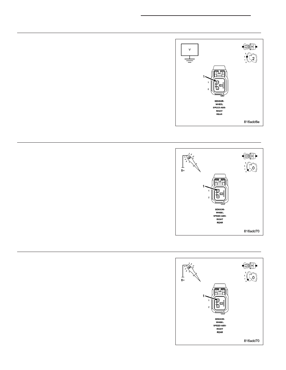
CHECK (B2) RIGHT REAR WSS 12 VOLT SUPPLY CIRCUIT VOLTAGE

If not done so previously, reconnect the Anti-Lock Brakes Module har-
ness connector.

Disconnect the Right Rear WSS harness connector.

Turn the ignition on.

Measure the voltage of the (B2) Right Rear WSS 12 Volt Supply circuit.

Is the voltage above 10.0 volts?

Yes

>> Go To 6

No

>> Go To 4

4.

CHECK (B2) RIGHT REAR WSS 12 VOLT SUPPLY CIRCUIT FOR A SHORT TO GROUND

Turn the ignition off.

Disconnect the Anti-Lock Brakes Module harness connector.

Using a 12-volt test light connected to 12 volts, probe the (B2) Right
Rear WSS 12 Volt Supply circuit.

Does the test light illuminate?

Yes

>> Repair the (B2) Right Rear WSS 12 Volt Supply circuit for a

short to ground.

Perform ABS VERIFICATION TEST - VER 1. (Refer to 5 -
BRAKES - STANDARD PROCEDURE).

No

>> Go To 5

5.

CHECK (B2) RIGHT REAR WSS 12 VOLT SUPPLY CIRCUIT FOR AN OPEN

Connect a jumper wire between ground and the (B2) Right Rear WSS
12 Volt Supply circuit in the Anti-Lock Brakes Module harness connec-
tor.

Using a 12-volt test light connected to 12 volts, probe the (B2) Right
Rear WSS 12 Volt Supply circuit.

Does the test light illuminate brightly?

Yes

>> Go To 6

No

>> Repair the (B2) Right Rear WSS 12 Volt Supply circuit for

an open.

Perform ABS VERIFICATION TEST - VER 1. (Refer to 5 -
BRAKES - STANDARD PROCEDURE).

5 - 92

BRAKES - ABS ELECTRICAL DIAGNOSTICS

KJ

6.

CHECK (B1) RIGHT REAR WSS SIGNAL CIRCUIT FOR A SHORT TO VOLTAGE

If not done so previously, turn the ignition on.

Measure the voltage of the (B1) Right Rear WSS Signal circuit.

Is the voltage above 1.0 volt?

Yes

>> Repair the (B1) Right Rear WSS Signal circuit for a short to

voltage.

Perform ABS VERIFICATION TEST - VER 1. (Refer to 5 -
BRAKES - STANDARD PROCEDURE).

No

>> Go To 7

7.

CHECK (B1) RIGHT REAR WSS SIGNAL CIRCUIT FOR A SHORT TO GROUND

Turn the ignition off.

If not done so previously, disconnect the Anti-Lock Brakes Module har-
ness connector.

Using a 12-volt test light connected to 12 volts, probe the (B1) Right
Rear WSS Signal circuit.

Does the test light illuminate?

Yes

>> Repair the (B1) Right Rear WSS Signal circuit for a short to

ground.

Perform ABS VERIFICATION TEST - VER 1. (Refer to 5 -
BRAKES - STANDARD PROCEDURE).

No

>> Go To 8

8.

CHECK (B1) RIGHT REAR WSS SIGNAL CIRCUIT FOR AN OPEN

Connect a jumper wire between ground and the (B1) Right Rear WSS
Signal circuit in the Anti-Lock Brakes Module harness connector.

Using a 12-volt test light connected to 12 volts, probe the (B1) Right
Rear WSS Signal circuit.

Does the test light illuminate brightly?

Yes

>> Go To 9

No

>> Repair the (B1) Right Rear WSS Signal circuit for an open.

Perform ABS VERIFICATION TEST - VER 1. (Refer to 5 -
BRAKES - STANDARD PROCEDURE).

KJ

BRAKES - ABS ELECTRICAL DIAGNOSTICS

5 - 93

9.

CHECK (B1) RIGHT REAR WSS SIGNAL CIRCUIT FOR A SHORT TO (B2) RIGHT REAR WSS 12 VOLT
SUPPLY CIRCUIT

If not done so previously, remove all jumper wires.

Measure the resistance between the (B1) Right Rear WSS Signal circuit
and the (B2) Right Rear WSS 12 Volt Supply circuit.

Is the resistance below 10k ohms?

Yes

>> Repair the (B1) Right Rear WSS Signal circuit for a short to

the (B2) Right Rear WSS 12 Volt Supply circuit.

Perform ABS VERIFICATION TEST - VER 1. (Refer to 5 -
BRAKES - STANDARD PROCEDURE).

No

>> Go To 10

10.

CHECK RIGHT REAR WSS

Reconnect the Anti-Lock Brakes Module harness connector.

Turn the ignition on.

Measure the voltage of the (B2) Right Rear WSS 12 Volt Supply circuit
while reconnecting the Right Rear WSS harness connector.

Did the voltage drop to 0 volts?

Yes

>> Replace the Right Rear WSS in accordance with the Ser-

vice Information.

Perform ABS VERIFICATION TEST - VER 1. (Refer to 5 -
BRAKES - STANDARD PROCEDURE).

No

>> Go To 11

11.

CHECK RIGHT REAR WSS OUTPUT

Backprobe the (B1) Right Rear WSS Signal circuit in the Right Rear
WSS harness connector with the positive lead of an ammeter.

Connect the ammeter negative lead to a good clean chassis ground.

Slowly rotate the right rear wheel.

Does the amperage toggle between 7 mA and 14 mA?

Yes

>> Replace the Anti-Lock Brakes Module in accordance with

the Service Information.

Perform ABS VERIFICATION TEST - VER 1. (Refer to 5 -
BRAKES - STANDARD PROCEDURE).

No

>> Replace the Right Rear WSS in accordance with the Ser-

vice Information.

Perform ABS VERIFICATION TEST - VER 1. (Refer to 5 -
BRAKES - STANDARD PROCEDURE).

5 - 94

BRAKES - ABS ELECTRICAL DIAGNOSTICS

KJ

C1032–RIGHT REAR WHEEL SPEED SENSOR SIGNAL ERRATIC PERFORMANCE

For a complete wiring diagram Refer to Section 8W.

When Monitored:
With the ignition on.

Set Condition:
If the Anti-Lock Brakes Module receives either an intermittent signal from the Right Rear WSS at a vehicle
speed above 35 km/h (22 m.p.h.), or an erratic signal from the Right Rear WSS during acceleration, or it
senses that the right rear wheel speed is different from other wheels.

Possible Causes

RIGHT REAR WSS LOOSE

RIGHT REAR WSS CIRCUITS, CONNECTORS, TERMINALS DAMAGED

RIGHT REAR TONE WHEEL DAMAGED OR WRONG NUMBER OF TEETH

EXCESSIVE AIR GAP BETWEEN RIGHT REAR WSS AND TONE WHEEL

RIGHT REAR WHEEL BEARING DAMAGED

RIGHT REAR BRAKE HARDWARE DAMAGED

RIGHT REAR WSS

ANTI-LOCK BRAKES MODULE

Diagnostic Test

1.

VERIFY IF DTC C102B–RIGHT REAR WHEEL SPEED SENSOR CIRCUIT IS ACTIVE

Turn the ignition on.

With the scan tool, record and erase ABS DTCs.

Cycle the ignition switch.

With the scan tool, read ABS DTCs.

NOTE: The Anti-Lock Brake Module must sense all 4 wheels at 25 km/h (15 m.p.h.) before it will extinguish
the ABS Indicator.

Does the scan tool display: C102B–RIGHT REAR WHEEL SPEED SENSOR CIRCUIT?

Yes

>> Diagnose and repair the DTC. Refer to the Table of Contents in this Section for a complete list of symp-

toms.

Perform ABS VERIFICATION TEST - VER 1. (Refer to 5 - BRAKES - STANDARD PROCEDURE).

No

>> Go To 2

2.

COMPARE WHEEL SPEED SENSOR SIGNALS

WARNING: Ensure brake capability is available before road testing.
With the scan tool, monitor ALL the WSS speeds while an assistant drives the vehicle.

Slowly accelerate as straight as possible from a stop to 40 km/h (25 m.p.h.).

Is the Right Rear WSS speed showing 0 km/h (0 m.p.h.) or not matching other wheel speeds?

Yes

>> Go To 3

No

>> Perform the ABS Intermittent Condition diagnostic procedure in this Section.

Perform ABS VERIFICATION TEST - VER 1. (Refer to 5 - BRAKES - STANDARD PROCEDURE).

KJ

BRAKES - ABS ELECTRICAL DIAGNOSTICS

5 - 95


Content   ..  831  832  833  834   ..