Jeep Liberty KJ. Manual - part 782


  Index      Jeep     Jeep Liberty KJ - service repair manual 2006 year


Search            


Content   ..  780  781  782  783   ..


Jeep Liberty KJ. Manual - part 782


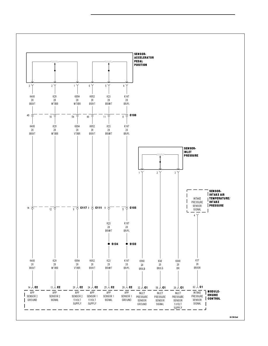
P0697-SENSOR SUPPLY 3 VOLTAGE TOO HIGH

For a complete wiring diagram Refer to Section 8W

9 - 1186

ENGINE DIESEL DIAG

KJ

When Monitored:
With the ignition on.

Set Condition:
The ECM detects a short to voltage for 0.1 second on the Sensor Supply #3 circuit which supplies 5-volts to
the Inlet Pressure Sensor and the APP Sensor #2.

Possible Causes

WIRING INSPECTION

INTERMITTENT CONDITION

APP SENSOR #2 5 VOLT SUPPLY CIRCUIT SHORTED TO VOLTAGE

ENGINE CONTROL MODULE

INLET PRESSURE SENSOR 5 VOLT SUPPLY CIRCUIT SHORTED TO VOLTAGE

Diagnostic Test

1.

CHECK FOR ACTIVE DTC

NOTE: If the ECM detects and stores a DTC, the ECM also stores the engine/vehicle operating conditions
under which the DTC was set. Some of these conditions are displayed on the scan tool at the same time the
DTC is displayed.

NOTE: Before erasing stored DTCs, record these conditions. Attempting to duplicate these conditions may
assist when checking for an active DTC.
Turn the ignition on.

With the scan tool, erase ECM DTCs.

Turn the ignition off for 10 seconds.

Turn the ignition on.

Monitor the scan tool for ECM DTCs.

Did this DTC reset?

Yes

>> Go To 2

No

>> Refer to the *CHECKING FOR AN INTERMITTENT DTC Diagnostic Procedure. (Refer to 9 - ENGINE -

DIAGNOSIS AND TESTING)

2.

APP #2 SENSOR 5-VOLT SUPPLY CIRCUIT SHORTED TO VOLTAGE

Turn the ignition off.

Disconnect the Accelerator Pedal Position Sensor harness connector.

Disconnect the ECM harness connectors.

Remove the ASD Relay from the PDC.

Connect a jumper wire between cavity 30 and cavity 87 of the ASD
Relay connector.

Turn the ignition on.

Measure the voltage on the Accelerator Pedal Position Sensor #2 5-Volt
Supply circuit.

NOTE: Remove the jumper wire and reinstall the ASD Relay.

Is the voltage below 1.0 volt?

Yes

>> Go To 3

No

>> Repair the APP #2 5-Volt Supply circuit for a short to volt-

age.

Perform the ECM Verification Test Ver. 1 (Refer to 9 -
ENGINE - DIAGNOSIS AND TESTING).

KJ

ENGINE DIESEL DIAG

9 - 1187

3.

INLET PRESSURE SENSOR 5-VOLT SUPPLY CIRCUIT SHORTED TO VOLTAGE

Turn the ignition off.

Disconnect the Inlet Pressure Sensor harness connector.

Disconnect the ECM harness connectors.

Remove the ASD Relay from the PDC.

Connect a jumper wire between cavity 30 and cavity 87 of the ASD
Relay connector.

Turn the ignition on.

Measure the voltage on the Inlet Pressure Sensor 5-Volt Supply circuit.

NOTE: Remove the jumper wire and reinstall the ASD Relay.

Is the voltage below 1.0 volt?

Yes

>> Go To 4

No

>> Repair the Inlet Pressure Sensor 5-Volt Supply circuit for a

short to voltage.

Perform the ECM Verification Test Ver. 1 (Refer to 9 -
ENGINE - DIAGNOSIS AND TESTING).

4.

WIRING INSPECTION

Turn the ignition off.

Inspect the Inlet Pressure Sensor 5-Volt supply circuit between the Inlet Pressure Sensor harness connector and the
ECM harness connector for possible shorts to other circuits.

Inspect the APP Sensor #2 5-Volt supply circuit between the APP Sensor harness connector and the ECM harness
connector for possible shorts to other circuits.

Were any problems found?

Yes

>> Repair shorted circuit as necessary.

Perform the ECM Verification Test Ver. 1 (Refer to 9 - ENGINE - DIAGNOSIS AND TESTING).

No

>> Replace and program the Engine Control Module in accordance with the Service Information.

Perform the ECM Verification Test Ver. 1 (Refer to 9 - ENGINE - DIAGNOSIS AND TESTING).

9 - 1188

ENGINE DIESEL DIAG

KJ

P0700-TCM DTC

For a complete wiring diagram Refer to Section 8W

When Monitored:
With the ignition on.

Set Condition:
The ECM recieves a CAN Bus message indicating the presence of a DTC in the TCM.

Possible Causes

VERIFY CURRENT DTC

Diagnostic Test

1.

VERIFY CURRENT DTC

NOTE: If the ECM detects and stores a DTC, the ECM also stores the engine/vehicle operating conditions
under which the DTC was set. Some of these conditions are displayed on the scan tool at the same time the
DTC is displayed.

NOTE: Before erasing stored DTCs, record these conditions. Attempting to duplicate these conditions may
assist when checking for an active DTC.

NOTE: This code was set in the ECM by the Transmission Control Module to indicate a transmission fault.
Diagnosis of transmission faults should be done using the Transmission Diagnostic Information.

NOTE: When repairs have been completed, the ECM and TCM must have codes cleared.
Turn the ignition on.

With the scan tool, erase ECM DTCs only.

With the scan tool, read ECM DTCs.

Are there any TCM DTCs present in the ECM?

Yes

>> Refer to Transmission Diagnostic Information for the related symptom(s).

Perform the ECM Verification Test Ver. 1 (Refer to 9 - ENGINE - DIAGNOSIS AND TESTING).

No

>> Test Complete.

KJ

ENGINE DIESEL DIAG

9 - 1189


Content   ..  780  781  782  783   ..