Jeep Liberty KJ. Manual - part 766
•
When Monitored:
With the ignition on.
•
Set Condition:
The ECM detects low voltage on the Sensor Supply #1 circuit which supplies 5-volts to the CMP Sensor and
the APP Sensor #1.
Possible Causes
WIRING INSPECTION
INTERMITTENT CONDITION
5-VOLT SUPPLY CIRCUIT SHORTED TO GROUND
ACCELERATOR PEDAL POSITION SENSOR
CAMSHAFT POSITION SENSOR
ENGINE CONTROL MODULE
Diagnostic Test
1.
CHECK FOR ACTIVE DTC
NOTE: If the ECM detects and stores a DTC, the ECM also stores the engine/vehicle operating conditions
under which the DTC was set. Some of these conditions are displayed on the scan tool at the same time the
DTC is displayed.
NOTE: Before erasing stored DTCs, record these conditions. Attempting to duplicate these conditions may
assist when checking for an active DTC.
Turn the ignition on.
With the scan tool, erase ECM DTCs.
Monitor the scan tool for ECM DTCs.
Did this DTC set again?
Yes
>> Go To 2
No
>> Refer to the *CHECKING FOR AN INTERMITTENT DTC Diagnostic Procedure. (Refer to 9 - ENGINE -
DIAGNOSIS AND TESTING)
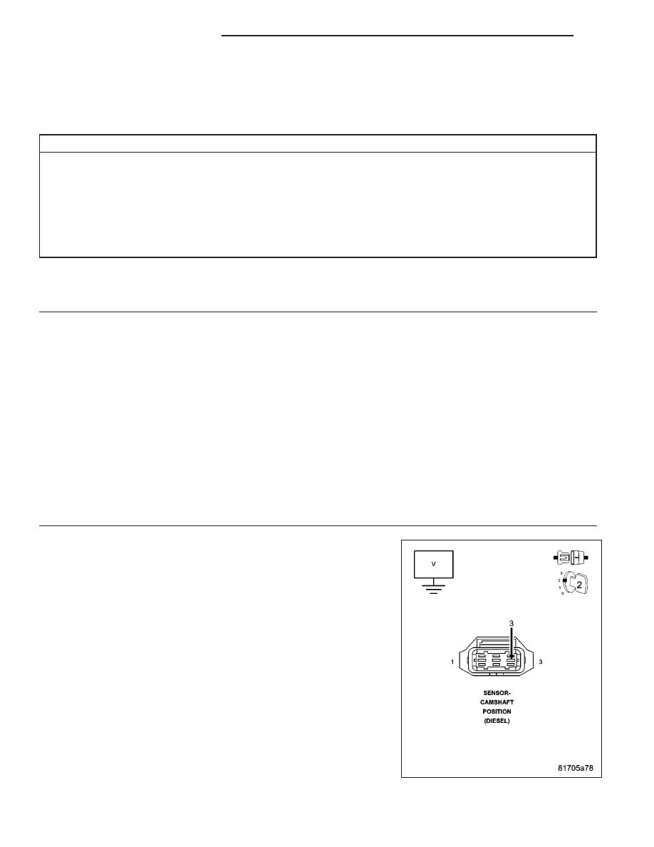
2.
CAMSHAFT POSITION SENSOR SHORTED TO GROUND
Turn the ignition off.
Disconnect the CMP Sensor harness connector.
Turn the ignition on.
Measure the voltage of the CMP Sensor 5-Volt Supply circuit.
Is the voltage above 4.6 volts?
Yes
>> Replace the Camshaft Position Sensor.
Perform the ECM Verification Test Ver. 1 (Refer to 9 -
ENGINE - DIAGNOSIS AND TESTING).
No
>> Go To 3
9 - 1122
ENGINE DIESEL DIAG
KJ