Jeep Liberty KJ. Manual - part 711
5.
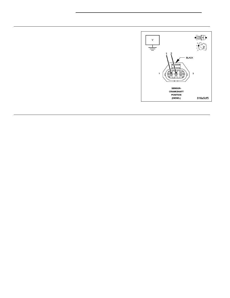
(K853, K3) CKP SENSOR SIGNAL CIRCUIT(S) SHORTED TO VOLTAGE
Remove the ASD Relay from the PDC.
Connect a jumper wire between cavity 30 and cavity 87 of the ASD
Relay connector.
Turn the ignition on.
Measure the voltage of both CKP Sensor Signal circuits.
Is the voltage below 1.0 volt for both measurements?
Yes
>> Go To 6
No
>> Repair the CKP Sensor Signal circuit(s) for a short to volt-
age.
Perform the ECM Verification Test Ver. 1 (Refer to 9 -
ENGINE - DIAGNOSIS AND TESTING).
6.
CRANKSHAFT POSITION SENSOR
Turn the ignition off.
Use a lab scope, backprobe both of the CKP Sensor Signal circuits at the ECM harness connector.
Start the engine, if the engine will not start, crank the engine for several seconds while monitoring the scan tool.
Does the lab scope display a steady clean CKP Signal pattern for each circuit?
Yes
>> Replace and program the Engine Control Module in accordance with the Service Information.
Perform the ECM Verification Test Ver. 1 (Refer to 9 - ENGINE - DIAGNOSIS AND TESTING).
No
>> Replace the Crankshaft Position Sensor.
Perform the ECM Verification Test Ver. 1 (Refer to 9 - ENGINE - DIAGNOSIS AND TESTING).
9 - 902
ENGINE DIESEL DIAG
KJ