Jeep Liberty KJ. Manual - part 631


  Index      Jeep     Jeep Liberty KJ - service repair manual 2006 year


Search            


Content   ..  629  630  631  632   ..


Jeep Liberty KJ. Manual - part 631


2.

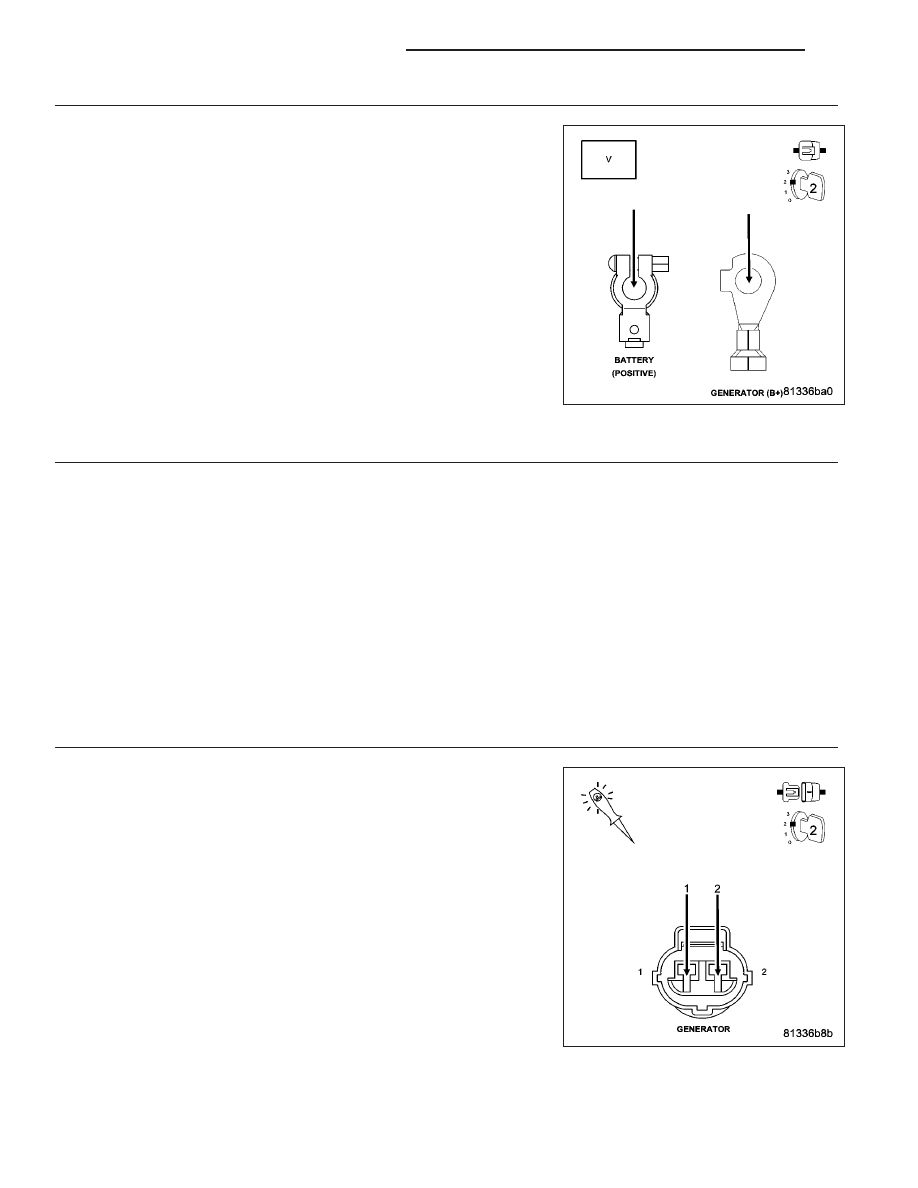
FUSED B+ CIRCUIT HIGH RESISTANCE

WARNING: When the engine is operating, do not stand in direct
line with the fan. Do not put your hands near the pulleys, belts, or
fan. Do not wear loose clothing. Failure to follow these instruc-
tions can result in personal injury or death.
Ignition on, engine not running.

NOTE: Make sure all wires are clear of the engine’s moving parts.
Measure the voltage between the Generator B+ Output Terminal and
the Battery+ Post.

Start the engine.

Is the voltage above 0.4 of a volt?

Yes

>> Repair the excessive resistance in the battery positive cir-

cuit between the Generator and Battery.

Perform the POWERTRAIN VERIFICATION TEST. (Refer to
9 - ENGINE - STANDARD PROCEDURE)

No

>> Go To 3

3.

EXCESSIVE RESISTANCE IN THE CASE GROUND

WARNING: When the engine is operating, do not stand in direct line with the fan. Do not put your hands
near the pulleys, belts, or fan. Do not wear loose clothing. Failure to follow these instructions can result in
personal injury or death.
Start the engine.

Warm the engine to operating temperature.

NOTE: Make sure all wires are clear of the engine’s moving parts.
Measure the voltage between the Generator Case and Battery ground post.

Is the voltage above 0.1 of a volt?

Yes

>> Repair the excessive resistance in the Generator Case Ground.

Perform the POWERTRAIN VERIFICATION TEST. (Refer to 9 - ENGINE - STANDARD PROCEDURE)

No

>> Go To 4

4.

GENERATOR OPERATION

Turn the ignition off.

Disconnect the Generator Field harness connector.

Using a 12-volt test light, jump across the Generator Field harness con-
nector.

Ignition on, engine not running.

With a scan tool, actuate the Generator Field Driver.

Does the test light illuminate brightly and flash on and off?

Yes

>> Replace the Generator.

Perform the POWERTRAIN VERIFICATION TEST. (Refer to
9 - ENGINE - STANDARD PROCEDURE)

No

>> Go To 5

9 - 582

ENGINE ELECTRICAL DIAGNOSTICS

KJ

5.

(K125) GEN FIELD CONTROL CIRCUIT SHORTED TO BATTERY VOLTAGE

Turn the ignition off.

Disconnect the C2 PCM harness connector.

Ignition on, engine not running.

Measure the voltage on the (K125) Gen Field Control circuit in the Gen-
erator Field harness connector.

Is the voltage above 1.0 volt?

Yes

>> Repair the short to battery voltage in the (K125) Gen Field

Control circuit.

Perform the POWERTRAIN VERIFICATION TEST. (Refer to
9 - ENGINE - STANDARD PROCEDURE)

No

>> Go To 6

6.

(K125) FIELD CONTROL CIRCUIT OPEN

Turn the ignition off.

CAUTION: Do not probe the PCM harness connectors. Probing the
PCM harness connectors will damage the PCM terminals resulting
in poor terminal to pin connection. Install Miller Special Tool #8815
to perform diagnosis.
Measure the resistance of the (K125) Gen Field Control circuit from the
Generator Field harness connector to the appropriate terminal of special
tool #8815.

Is the resistance below 5.0 ohms?

Yes

>> Go To 7

No

>> Repair the open in the (K125) Gen Field Control circuit.

Perform the POWERTRAIN VERIFICATION TEST. (Refer to
9 - ENGINE - STANDARD PROCEDURE)

7.

(K125) GEN FIELD CONTROL CIRCUIT SHORTED TO GROUND

Measure the resistance between ground and the (K125) Gen Field Con-
trol circuit in the Generator Field harness connector.

Is the resistance below 100 ohms?

Yes

>> Repair the short to ground in the (K125) Gen Field Control

circuit.

Perform the POWERTRAIN VERIFICATION TEST. (Refer to
9 - ENGINE - STANDARD PROCEDURE)

No

>> Go To 8

KJ

ENGINE ELECTRICAL DIAGNOSTICS

9 - 583

8.

(Z932) GROUND CIRCUIT OPEN

Using a 12-volt test light connected to battery voltage, probe the (Z932)
Ground circuit in the Generator Field harness connector.

Does the test light illuminate brightly?

Yes

>> Go To 9

No

>> Repair the open in the (Z932) Generator Ground circuit.

Perform the POWERTRAIN VERIFICATION TEST. (Refer to
9 - ENGINE - STANDARD PROCEDURE)

9.

PCM

NOTE: Before continuing, check the PCM harness connector terminals for corrosion, damage, or terminal
push out. Repair as necessary.
Using the schematics as a guide, inspect the wire harness and connectors. Pay particular attention to all Power and
Ground circuits.

Were there any problems found?

Yes

>> Repair as necessary.

Perform the POWERTRAIN VERIFICATION TEST. (Refer to 9 - ENGINE - STANDARD PROCEDURE)

No

>> Replace and program the Powertrain Control Module per Service Information.

Perform the POWERTRAIN VERIFICATION TEST. (Refer to 9 - ENGINE - STANDARD PROCEDURE)

U0001–CAN C BUS

For a complete wiring diagram Refer to Section 8W.

When Monitored:
With the ignition on.

Set Condition:
If the Anti-Lock Brakes Module detects a short in either CAN C Bus circuit.

Perform CAN C Bus Communication Failure diagnostic test procedure. (Refer to 8 - ELECTRICAL/ELECTRONIC
CONTROL MODULES - DIAGNOSIS AND TESTING)
.

9 - 584

ENGINE ELECTRICAL DIAGNOSTICS

KJ

U0101–LOST COMMUNICATION WITH TCM

For a complete wiring diagram Refer to Section 8W.

When Monitored:

With the ignition on

Battery voltage between 10 and 16 volts

IOD fuse installed

Set Condition:
If the Anti-Lock Brakes Module fails to receive bus messages from the TCM for approximately 500 ms.

Possible Causes

DTCS RELATED TO BATTERY VOLTAGE, IGNITION, OR VIN MESSAGES

CAN C BUS CIRCUITS OPEN OR SHORTED

TCM POWER AND GROUND

TCM

ANTI-LOCK BRAKES MODULE

Diagnostic Test

1.

VERIFY DTC IS ACTIVE

NOTE: Ensure the IOD fuse is installed and battery voltage is between 10 and 16 volts before proceeding.
Turn the ignition on.

With the scan tool, read active DTCs.

Is this DTC active?

Yes

>> Go To 2

No

>> Perform the Stored Lost Communication test procedure. (Refer to 8 - ELECTRICAL/ELECTRONIC

CONTROL MODULES - DIAGNOSIS AND TESTING).

2.

CHECK FOR ANY OF THE FOLLOWING ACTIVE DTCS

With the scan tool, read all active DTCs from all CAN C Bus modules.

NOTE: Check for CAN C hardware electrical, VIN Missing/Mismatch, battery or ignition related DTCs.

Does the scan tool display any active DTCs to the conditions listed above?

Yes

>> Diagnose and repair the DTC(s). Refer to the Table of Contents in the applicable Section.

No

>> Go To 3

3.

VERIFY THAT THE TCM IS ACTIVE ON THE BUS

With the scan tool, select ECU View.

Verify that the TCM is active on the bus.

Is the TCM active on the bus?

Yes

>> Go To 4

No

>> (Refer to 8 - ELECTRICAL/ELECTRONIC CONTROL MODULES - DIAGNOSIS AND TESTING) for No

Response related diagnostic procedures.

KJ

ENGINE ELECTRICAL DIAGNOSTICS

9 - 585


Content   ..  629  630  631  632   ..