Jeep Liberty KJ. Manual - part 494


  Index      Jeep     Jeep Liberty KJ - service repair manual 2006 year


Search            


Content   ..  492  493  494  495   ..


Jeep Liberty KJ. Manual - part 494


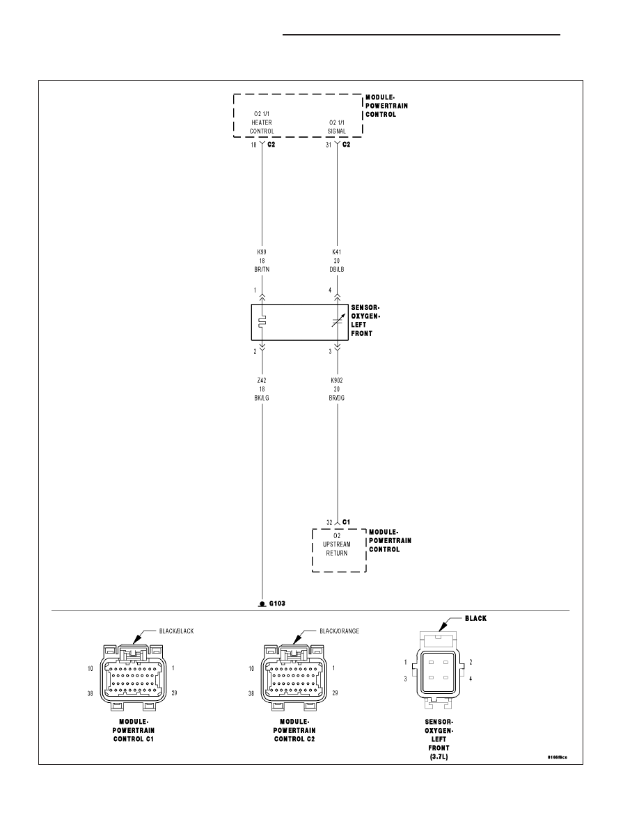
P0135-O2 SENSOR 1/1 HEATER PERFORMANCE

For a complete wiring diagram Refer to Section 8W.

9 - 134

ENGINE ELECTRICAL DIAGNOSTICS

KJ

Theory of Operation

This diagnostic provides a continuous check of the O2 heater circuit during operation. The heater circuit is momen-
tarily disabled to allow a resistance measurement to be taken to infer heater temperature. The current delivery to
the heater is duty cycled to maintain a specific target temperature. The error from the target temperature is contin-
uously monitored to assess heater performance.

When Monitored:
Engine running and heater duty cycle greater than 0%. Battery voltage greater than 11.0 volts.

Set Condition:
No sensor output is received when the PCM powers up the sensor heater. Two trip fault. Three good trips to
turn off the MIL.

Possible Causes

(K99) O2 1/1 HEATER CONTROL CIRCUIT OPEN

(Z42) O2 1/1 HEATER GROUND CIRCUIT OPEN

O2 SENSOR HEATER ELEMENT

PCM

Always perform the Pre-Diagnostic Troubleshooting procedure before proceeding. (Refer to 9 - ENGINE -
DIAGNOSIS AND TESTING).

Diagnostic Test

1.

O2 SENSOR HEATER OPERATION

Turn the ignition off.

NOTE: Wait a minimum of 8 minutes to allow the O2 Sensor to cool down before continuing the test. Allow
the O2 Sensor voltage to stabilize between 4.6 and 5.0 volts.
Ignition on, engine not running.

With a scan tool, actuate the O2 Heater Test.

With the scan tool, monitor 1/1 O2 Sensor voltage for at least 2 minutes.

Does the voltage stay above 4.5 volts?

Yes

>> Go To 2

No

>> Refer to the INTERMITTENT CONDITION Diagnostic Procedure.

Perform the POWERTRAIN VERIFICATION TEST. (Refer to 9 - ENGINE - STANDARD PROCEDURE)

2.

O2 SENSOR HEATER ELEMENT

Turn the ignition off.

NOTE: Allow the O2 sensor to cool down to room temperature.
Disconnect the O2 Sensor harness connector.

Measure the resistance of the O2 Heater Element across the 1/1 O2 Sensor connector between the O2 Heater
Control terminal and the Heater ground terminal.

NOTE: O2 Heater Element resistance values should be measured at 70°F (21.1°C). The resistance value will
vary with different temperature values.

Is the resistance of the O2 Sensor Heater Element between 2.0 and 30.0 ohms?

Yes

>> Go To 3

No

>> Replace the O2 Sensor.

Perform the POWERTRAIN VERIFICATION TEST. (Refer to 9 - ENGINE - STANDARD PROCEDURE)

KJ

ENGINE ELECTRICAL DIAGNOSTICS

9 - 135

3.

(K99) O2 1/1 HEATER CONTROL CIRCUIT OPEN

Disconnect the C2 PCM harness connector.

CAUTION: Do not probe the PCM harness connectors. Probing the
PCM harness connectors will damage the PCM terminals resulting
in poor terminal to pin connection. Install Miller Special Tool #8815
to perform diagnosis.
Measure the resistance of the (K99) O2 1/1 Heater Control circuit from
the O2 harness connector to the appropriate terminal of special tool
#8815.

Is the resistance below 0.5 of an ohm?

Yes

>> Go To 4

No

>> Repair the excessive resistance in the (K99) O2 1/1 Heater

Control circuit.

Perform the POWERTRAIN VERIFICATION TEST. (Refer to
8 - ELECTRICAL/ELECTRONIC CONTROL MODULES/
POWERTRAIN CONTROL MODULE - DIAGNOSIS AND
TESTING)

4.

(Z42) O2 1/1 HEATER GROUND CIRCUIT OPEN

Measure the resistance between ground and the (Z42) O2 1/1 Heater
ground circuit in the O2 Sensor harness connector.

Is the resistance below 0.5 of an ohm?

Yes

>> Go To 5

No

>> Repair the excessive resistance in the (Z42) O2 1/1 Heater

ground circuit.

Perform the POWERTRAIN VERIFICATION TEST. (Refer to
9 - ENGINE - STANDARD PROCEDURE)

5.

PCM

NOTE: Before continuing, check the PCM harness connector terminals for corrosion, damage, or terminal
push out. Repair as necessary.
Using the schematics as a guide, inspect the wire harness and connectors. Pay particular attention to all Power and
Ground circuits.

Were there any problems found?

Yes

>> Repair as necessary.

Perform the POWERTRAIN VERIFICATION TEST. (Refer to 9 - ENGINE - STANDARD PROCEDURE)

No

>> Replace and program the Powertrain Control Module per Service Information.

Perform the POWERTRAIN VERIFICATION TEST. (Refer to 9 - ENGINE - STANDARD PROCEDURE)

9 - 136

ENGINE ELECTRICAL DIAGNOSTICS

KJ

P0137-O2 SENSOR 1/2 CIRCUIT LOW

For a complete wiring diagram Refer to Section 8W.

KJ

ENGINE ELECTRICAL DIAGNOSTICS

9 - 137


Content   ..  492  493  494  495   ..