Jeep Liberty KJ. Manual - part 470
3.
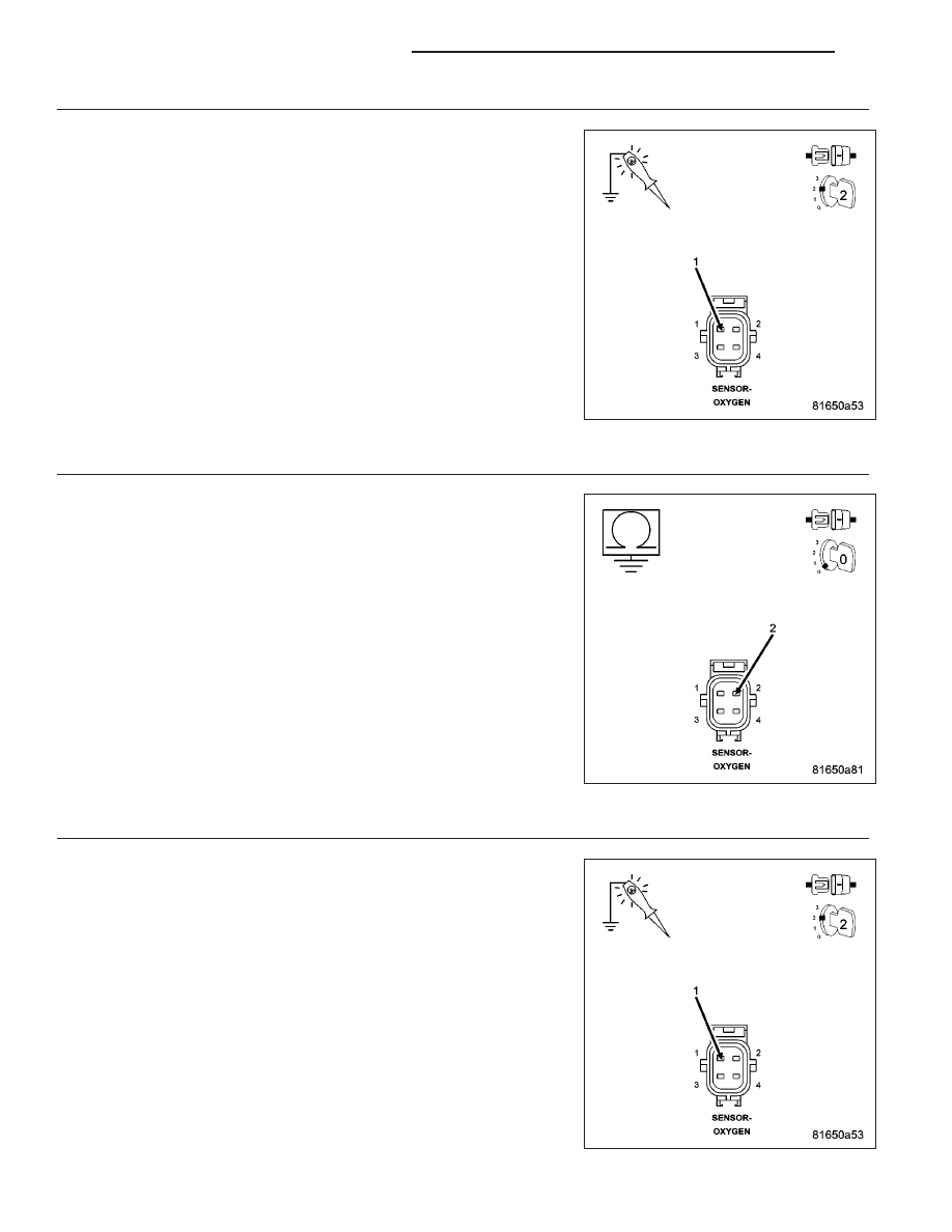
(K399) O2 2/2 HEATER CONTROL CIRCUIT
Ignition on, engine not running.
With a scan tool, actuate the O2 2/2 Heater Test with the Sensor har-
ness connector still disconnected.
Using a 12-volt test light connected to ground, probe the (K399) O2 2/2
Heater Control circuit in the O2 Sensor harness connector.
Does the test light illuminate brightly and flash on and off dur-
ing the actuation?
Yes
>> Go To 4
No
>> Go To 5
4.
(Z42) O2 HEATER GROUND CIRCUIT OPEN
Turn the ignition off.
Measure the resistance between an engine ground and the (Z42) O2
2/2 Heater ground circuit in the O2 Sensor harness connector.
Is the resistance below 5.0 ohms?
Yes
>> Replace the O2 Sensor.
Perform the POWERTRAIN VERIFICATION TEST. (Refer to
9 - ENGINE - STANDARD PROCEDURE)
No
>> Repair the open in the (Z42) O2 2/2 Heater ground circuit.
Perform the POWERTRAIN VERIFICATION TEST. (Refer to
9 - ENGINE - STANDARD PROCEDURE)
5.
(K399) O2 2/2 HEATER CONTROL CIRCUIT SHORTED TO BATTERY VOLTAGE
Turn the ignition off.
Disconnect the C3 PCM harness connector.
Ignition on, engine not running.
Using a 12-volt test light connected to ground, probe the (K399) O2
Heater 2/2 Control circuit in the O2 Sensor harness connector.
Does the test light illuminate?
Yes
>> Repair the short to battery voltage in the (K399) O2 2/2
Heater Control circuit.
Perform the POWERTRAIN VERIFICATION TEST. (Refer to
9 - ENGINE - STANDARD PROCEDURE)
No
>> Go To 6
9 - 38
ENGINE ELECTRICAL DIAGNOSTICS
KJ