Jeep Liberty KJ. Manual - part 318


  Index      Jeep     Jeep Liberty KJ - service repair manual 2006 year


Search            


Content   ..  316  317  318  319   ..


Jeep Liberty KJ. Manual - part 318


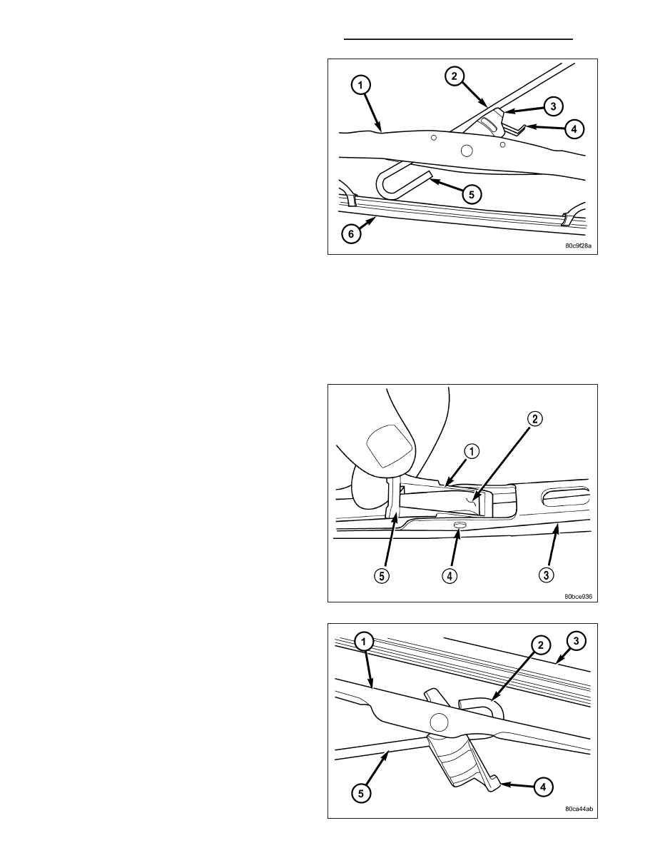
1. Lift the front wiper arm (2) to raise the wiper blade

and element off of the glass, until the wiper arm
hinge is in its over-center position.

2. To remove the wiper blade from the wiper arm,

depress the pivot block latch release tab (4) under
the tip of the arm and slide the blade away from
the tip towards the pivot end of the arm far enough
to disengage the pivot block (3) from the hook for-
mation (5) on the end of the arm.

3. Extract the hook formation on the tip of the wiper

arm through the opening in the wiper blade super-
structure (1) just ahead of the wiper blade pivot
block/latch unit.

CAUTION: Do not allow the wiper arm to spring
back against the glass without the wiper blade in
place or the glass may be damaged.

4. Gently lower the tip of the wiper arm onto the glass.

REAR

NOTE: The notched end of the wiper element flexor should always be oriented towards the end of the wiper
blade that is nearest to the rear wiper motor output shaft.

1. Disengage the rear wiper arm support from the

rear wiper arm park ramp on the right side of the
tailgate just below the rear flip-up glass.

2. Lift the rear wiper arm to raise the wiper blade and

element off of the tailgate and the rear flip-up
glass.

3. To remove the wiper blade from the wiper arm,

carefully lift up the pivot block latch release tab (5)
on the top of the wiper arm to unlatch it from the
arm (2).

4. Raise the pivot block latch release tab (4) until it is

perpendicular to the rear wiper blade superstruc-
ture (1).

5. Slide the rear wiper blade away from the tip of the

arm towards the pivot end of the arm far enough to
disengage the pivot block from the hook formation
(2) on the end of the arm (5).

6. Extract the hook formation on the tip of the wiper

arm from the window in the wiper blade pivot block/
latch unit.

CAUTION: Do not allow the wiper arm to spring
back against the tailgate or the flip-up glass with-
out the wiper blade in place or they may be dam-
aged.

8R - 64

WIPERS/WASHERS - SERVICE INFORMATION

KJ

7. Gently lower the wiper arm and place the arm support in the park ramp.

INSTALLATION

FRONT

NOTE: The notched end of the wiper element
flexor should always be oriented towards the end
of the wiper blade that is nearest to the wiper
pivot.

1. Lift the front wiper arm (2) off of the windshield

glass, until the wiper arm hinge is in its over-center
position.

2. Position the front wiper blade near the hook forma-

tion (5) on the tip of the arm with the notched end
of the wiper element flexor oriented towards the
end of the wiper arm that is nearest to the wiper
pivot.

3. Insert the hook formation on the tip of the wiper

arm through the opening in the wiper blade super-
structure (1) ahead of the wiper blade pivot block/
latch unit far enough to engage the pivot block (3) into the hook.

4. Slide the wiper blade pivot block/latch up into the hook formation on the tip of the wiper arm until the latch

release tab (4) snaps into its locked position. Latch engagement will be accompanied by an audible click.

5. Gently lower the wiper blade onto the glass.

REAR

NOTE: The notched end of the wiper element flexor should always be oriented towards the end of the wiper
blade that is nearest to the rear wiper motor output shaft.

1. Lift the rear wiper arm support out of the tail gate

park ramp.

2. Position the rear wiper blade (1) near the hook for-

mation (2) on the tip of the arm (5) with the
notched end of the wiper element (3) flexor ori-
ented towards the end of the wiper arm that is
nearest to the rear wiper motor output shaft.

3. Raise the pivot block latch release tab (4) until it is

perpendicular to the rear wiper blade superstruc-
ture.

4. Insert the hook formation on the tip of the wiper

arm through the window in the wiper blade pivot
block/latch unit.

5. Slide the wiper blade pivot block/latch up into the

hook formation on the tip of the wiper arm until the
hook is firmly seated against the pivot block.

6. Press the pivot block latch release tab downward until it snaps into its locked position over the top of the wiper

arm.

7. Gently lower the wiper arm and place the arm support in the tailgate park ramp.

KJ

WIPERS/WASHERS - SERVICE INFORMATION

8R - 65

WIPER HIGH/LOW RELAY

DESCRIPTION

The wiper high/low relay is located in the Power Dis-
tribution Center (PDC) in the engine compartment
near the battery. The wiper high/low relay is a conven-
tional

International

Standards

Organization

(ISO)

micro relay. Relays conforming to the ISO specifica-
tions have common physical dimensions, current
capacities, terminal patterns, and terminal functions.
The relay is contained within a small, rectangular,
molded plastic housing and is connected to all of the
required inputs and outputs by five integral male
spade-type terminals that extend from the bottom of
the relay base.

The wiper high/low relay cannot be adjusted or repaired and, if inoperative or damaged, the unit must be replaced.

OPERATION

The wiper high/low relay is an electromechanical switch that uses a low current input from the Body Control Module
(BCM) to control a high current output to the front wiper motor. The movable common feed contact point is held
against the fixed normally closed contact point by spring pressure. When the relay coil is energized, an electromag-
netic field is produced by the coil windings. This electromagnetic field draws the movable relay contact point away
from the fixed normally closed contact point, and holds it against the fixed normally open contact point. When the
relay coil is de-energized, spring pressure returns the movable contact point back against the fixed normally closed
contact point. A resistor is connected in parallel with the relay coil in the relay, and helps to dissipate voltage spikes
and electromagnetic interference that can be generated as the electromagnetic field of the relay coil collapses.

The wiper high/low relay terminals are connected to the vehicle electrical system through a connector receptacle in
the Power Distribution Center (PDC). The inputs and outputs of the wiper high/low relay include:

Common Feed Terminal - The common feed terminal (30) is connected to the common feed terminal (30) of
the wiper on/off relay at all times through the wiper on/off relay output circuit. Therefore, the wiper high/low
relay common feed terminal is only powered when the wiper on/off relay is energized.

Coil Ground Terminal - The coil ground terminal (85) is connected to a control output of the Body Control
Module (BCM) through the front wiper high/low relay control circuit. The BCM controls front wiper motor oper-
ation by controlling a ground path through this circuit.

Coil Battery Terminal - The coil battery terminal (86) receives battery current at all times from a circuit
breaker in the Junction Block (JB) through a fused ignition switch output (run-acc) circuit.

Normally Open Terminal - The normally open terminal (87) is connected to the high speed brush of the front
wiper motor through the front wiper high/low relay high speed output circuit. Therefore, when the wiper high/
low relay is energized, the wiper motor high speed brush is powered.

Normally Closed Terminal - The normally closed terminal (87A) is connected to the low speed brush of the
front wiper motor through the front wiper high/low relay low speed output circuit. Therefore, the wiper motor
low speed brush can only be powered when the wiper high/low relay is de-energized.

The wiper high/low relay can be diagnosed using conventional diagnostic tools and methods.

8R - 66

WIPERS/WASHERS - SERVICE INFORMATION

KJ

WIPER MODULE

DESCRIPTION

The front wiper module bracket is secured with two
nuts below the wiper motor through rubber insulators
(7) to two weld studs on the bottom of the cowl ple-
num panel beneath the cowl plenum cover/grille panel.
Two screws secure the top of the module bracket to
the cowl plenum panel through rubber insulators
located on the outboard end of each pivot bracket.
The ends of the wiper pivot shafts that protrude
through dedicated openings in the cowl plenum cover/
grille panel to drive the wiper arms and blades are the
only visible components of the front wiper module. The
front wiper module consists of the following major
components:

Bracket - The front wiper module bracket consists of a long tubular steel main member (2) that has a die cast
pivot bracket (1) formation near each end where the two wiper pivots are secured. A stamped steel mounting
plate (3) for the wiper motor is secured with welds near the center of the main member. A short stamped steel
tab that extends laterally from one side of the mounting plate provides a mounting location for the wiper motor
pigtail wire connector (10).

Crank Arm (9) - The front wiper motor crank arm is a stamped steel unit with a slotted hole on the driven end
that is secured to the wiper motor output shaft with a nut, and has a ball stud secured to the drive end.

Linkage (5) - Two stamped steel drive links connect the wiper motor crank arm to the wiper pivot lever arms.
The right side drive link has a plastic socket-type bushing (4) on each end. The left side drive link has a plastic
socket-type bushing on one end, and a plastic sleeve-type bushing on the other end. The socket-type bushing
on one end of each drive link is snap-fit over the ball stud on the lever arm of its respective pivot. The left side
drive link sleeve-type bushing end is then fit over the motor crank arm ball stud, and the other socket-type
bushing of the right side drive link is snap-fit over the exposed end of the wiper motor crank arm ball stud.

Motor - The front wiper motor is secured with three screws to the motor mounting plate near the center of the
wiper module bracket. The wiper motor output shaft passes through a hole in the module bracket, where a nut
secures the wiper motor crank arm to the motor output shaft. The two-speed permanent magnet wiper motor
features an integral transmission, an internal park switch, and an internal automatic resetting circuit breaker.

Pivots - The two front wiper pivots are secured within the die cast pivot brackets on the outboard ends of the
wiper module main member. The lever arms (8) that extend from the center of the pivot shafts (6) each have
a ball stud on their end. The upper end of each pivot shaft where the wiper arms will be fastened each is
tapered and serrated with a threaded stud formation at the tip. The lower ends of the pivot shafts are installed
through lubricated bushings in the pivot brackets and are secured with snap rings.

The front wiper module cannot be adjusted or repaired. If any component of the module is inoperative or damaged,
the entire front wiper module unit must be replaced.

OPERATION

The front wiper module operation is controlled by the battery current inputs received by the wiper motor from the
wiper on/off and wiper high/low relays. The wiper motor speed is controlled by current flow to either the low speed
or the high speed set of brushes. The park switch is a single pole, single throw, momentary switch within the wiper
motor that is mechanically actuated by the wiper motor transmission components. The park switch alternately closes
the wiper park switch sense circuit to ground or to battery current, depending upon the position of the wipers on the
glass. This feature allows the motor to complete its current wipe cycle after the wiper system has been turned Off,
and to park the wiper blades in the lowest portion of the wipe pattern. The automatic resetting circuit breaker pro-
tects the motor from overloads. The wiper motor crank arm, the two wiper linkage members, and the two wiper
pivots mechanically convert the rotary output of the wiper motor to the back and forth wiping motion of the wiper
arms and blades on the glass.

KJ

WIPERS/WASHERS - SERVICE INFORMATION

8R - 67


Content   ..  316  317  318  319   ..