Jeep Liberty KJ. Manual - part 277


  Index      Jeep     Jeep Liberty KJ - service repair manual 2006 year


Search            


Content   ..  275  276  277  278   ..


Jeep Liberty KJ. Manual - part 277


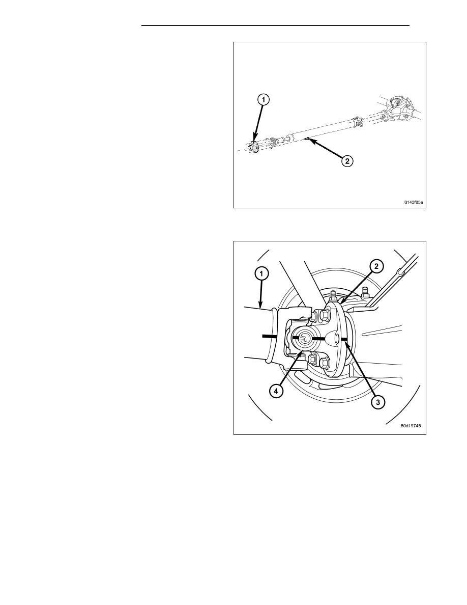
4. On 4x2 vehicles with manual transmission remover

transmission companion flange (1) bolts (2).

5. Remove pinion companion flange bolts.

6. Remove propeller shaft.

INSTALLATION

1. Slide slip yoke on the transmission/transfer case

output shaft. On 4x2 vehicles with a manual trans-
mission install transmission flange bolts and tighten
to 115 N·m (85 ft. lbs.).

2. Align reference marks (3) on companion flanges (2)

(4) and propeller shaft (1).

3 - 12

PROPELLER SHAFT

KJ

3. Install companion flange bolts and tighten to 115

N·m (85 ft. lbs.).

4. Tighten dust boot (3) clamps (4) if equipped with

clamp installer (1).

KJ

PROPELLER SHAFT

3 - 13

UNIVERSAL JOINT-SINGLE CARDAN

DISASSEMBLY - WITH SNAP RINGS

NOTE: This procedure describes a propeller shaft
equipped with a cardan joint in the tube yoke. For
propeller shafts equipped with a companion/slip
yoke, repeat the steps to remove the remaining
cardan joint.

1. Tap outside of bearing cap with a drift to loosen

snap ring.

2. Remove snap rings (1) from both sides of yoke.

3. Position yoke with the grease fitting if equipped,

pointing up.

4. Position a socket (2) with a inside diameter large

enough to receive the bearing cap, beneath the
yoke on a press.

5. Place another socket (2) with an outside diameter

smaller than bearing cap on the upper bearing cap
and press (1) the lower cap through the yoke.

3 - 14

PROPELLER SHAFT

KJ

NOTE: If the bearing cap will not pull out of the
yoke by hand after pressing, tap the yoke ear near
the bearing cap to dislodge the cap.

6. Pull bearing cap of the yoke.

7. Turn yoke over in the press and straighten the

cross (1). Press the cross until the remaining bear-
ing cap (2) can be removed.

CAUTION: If cross or bearing cap are not straight
during removal, the bearing cap will score the
walls of the yoke bore and damage can occur.

ASSEMBLY - WITH SNAP RINGS

NOTE: This procedure describes a propeller shaft
equipped a cardan joint in the tube yoke. For pro-
peller shafts equipped with a companion/slip yoke,
repeat the steps to remove the remaining cardan
joint.

1. Apply (EP) N.L.G.I. Grade 1 or 2 grease to inside

of yoke bores.

2. Position cross (1) in yoke (2) with lube fitting point-

ing up, if equipped.

KJ

PROPELLER SHAFT

3 - 15


Content   ..  275  276  277  278   ..