Jeep Liberty KJ. Manual - part 259


  Index      Jeep     Jeep Liberty KJ - service repair manual 2006 year


Search            


Content   ..  257  258  259  260   ..


Jeep Liberty KJ. Manual - part 259


5.

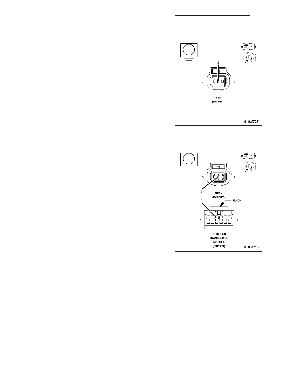
CHECK THE (X75) SIREN SIGNAL CONTROL CIRCUIT FOR A SHORT TO GROUND

Turn the ignition off.

Disconnect the ITM harness connector.

Measure the resistance between ground and the (X75) Siren Signal
Control circuit in the Siren harness connector.

Is the resistance below 100.0 ohms?

Yes

>> Repair the (X75) Siren Signal Control circuit for a short to

ground.

Perform VTSS VERIFICATION TEST - 1A. (Refer to VTSS
VERIFICATION TEST - 1A - STANDARD PROCEDURE) in
this Section.

No

>> Go To 6

6.

CHECK THE (X75) SIREN SIGNAL CONTROL CIRCUIT FOR AN OPEN

Measure the resistance of the (X75) Siren Signal Control circuit
between the ITM harness connector and the Siren harness connector.

Is the resistance below 5.0 ohms?

Yes

>> Replace the ITM in accordance with the Service Informa-

tion.

Perform BODY VERIFICATION TEST - VER 1. (Refer to 8 -
ELECTRICAL/ELECTRONIC

CONTROL

MODULES

-

STANDARD PROCEDURE).

No

>> Repair the (X75) Siren Signal Control circuit for an open.

Perform VTSS VERIFICATION TEST - 1A. (Refer to VTSS
VERIFICATION TEST - 1A - STANDARD PROCEDURE) in
this Section.

8Q - 12

VEHICLE THEFT SECURITY - ELECTRICAL DIAGNOSTICS

KJ

ITM–PCM MESSAGE NOT RECEIVED (EXPORT ONLY)

For a complete wiring diagram Refer to Section 8W

When Monitored:
With the ignition on.

Set Condition:
The Intrusion Transceiver Module (ITM) fails to receive bus messages from the Powertrain Control Module
(PCM).

Possible Causes

BUS COMMUNICATION FAILURE

INTRUSION TRANSCEIVER MODULE (ITM)

Diagnostic Test

1.

VERIFY THAT THE PCM AND BCM ARE ACTIVE ON THE BUS

Turn the ignition on.

With the scan tool, verify that the PCM and BCM are active on the bus.

Are both modules active on the bus?

Yes

>> Go To 2

No

>> Refer to (Refer to 8 - ELECTRICAL/ELECTRONIC CONTROL MODULES - DIAGNOSIS AND TEST-

ING) for No Response related diagnostic procedures.

2.

VERIFY THAT THE DTC IS ACTIVE

With the scan tool, erase ITM DTCs.

Turn the ignition off.

Arm the VTSS and wait one minute.

Disarm the VTSS and turn the ignition on.

With the scan tool, read ITM DTCs.

Did this DTC reset?

Yes

>> Replace the ITM in accordance with the service information.

Perform BODY VERIFICATION TEST - VER 1. (Refer to 8 - ELECTRICAL/ELECTRONIC CONTROL
MODULES - STANDARD PROCEDURE).

No

>> The condition that caused this symptom is currently not present. Inspect the related wiring harness for

a possible intermittent condition. Look for any chafed, pierced or partially broken wires.

Perform BODY VERIFICATION TEST - VER 1. (Refer to 8 - ELECTRICAL/ELECTRONIC CONTROL
MODULES - STANDARD PROCEDURE).

KJ

VEHICLE THEFT SECURITY - ELECTRICAL DIAGNOSTICS

8Q - 13

ITM–PRE-ARM TIMEOUT FAILURE (EXPORT ONLY)

For a complete wiring diagram Refer to Section 8W

When Monitored:
During the VTSS pre-arm process.

Set Condition:
If the Intrusion Transceiver Module (ITM) fails to receive the arm message from the Body Control Module
(BCM) after sixty seconds.

Possible Causes

BUS COMMUNICATION FAILURE

INTRUSION TRANSCEIVER MODULE (ITM)

Diagnostic Test

1.

VERIFY THAT THE BCM IS ACTIVE ON THE BUS

Turn the ignition on.

With the scan tool, verify that the BCM is active on the bus.

Is the BCM active on the bus?

Yes

>> Go To 2

No

>> Refer to (Refer to 8 - ELECTRICAL/ELECTRONIC CONTROL MODULES - DIAGNOSIS AND TEST-

ING) for no response related diagnostic procedures.

2.

VERIFY THAT THE DTC IS ACTIVE

With the scan tool, erase ITM DTCs.

Turn the ignition off.

Arm the VTSS and wait one minute.

Disarm the VTSS and turn the ignition on.

With the scan tool, read ITM DTCs.

Did this DTC reset?

Yes

>> Replace the ITM in accordance with the service information.

Perform BODY VERIFICATION TEST - VER 1. (Refer to 8 - ELECTRICAL/ELECTRONIC CONTROL
MODULES - STANDARD PROCEDURE).

No

>> The condition that caused this symptom is currently not present. Inspect the related wiring harness for

a possible intermittent condition. Look for any chafed, pierced or partially broken wires.

Perform BODY VERIFICATION TEST - VER 1. (Refer to 8 - ELECTRICAL/ELECTRONIC CONTROL
MODULES - STANDARD PROCEDURE).

8Q - 14

VEHICLE THEFT SECURITY - ELECTRICAL DIAGNOSTICS

KJ

ITM–SIREN BATTERY HAS BEEN TAMPERED (EXPORT ONLY)

For a complete wiring diagram Refer to Section 8W

When Monitored:
Continuously while the VTSS is armed.

Set Condition:
If the siren detects the loss of vehicle battery voltage.

Possible Causes

SIREN WIRE HARNESS TAMPERED WITH OR DAMAGED

INTRUSION TRANSCEIVER MODULE (ITM)

Diagnostic Test

1.

INSPECT THE SIREN WIRE HARNESS SIGNS OF TAMPERING AND DAMAGE

Turn the ignition off.

Inspect the wiring harness to the siren for signs of tampering and damage.

Were any problems found?

Yes

>> Repair as necessary.

Perform VTSS VERIFICATION TEST - 1A. (Refer to VTSS VERIFICATION TEST - 1A - STANDARD
PROCEDURE) in this Section.

No

>> Go To 2

2.

VERIFY THAT THE DTC IS ACTIVE

Turn the ignition on.

With the scan tool, erase ITM DTCs.

Turn the ignition off.

Arm the VTSS and wait one minute.

Disarm the VTSS and turn the ignition on.

With the scan tool, read ITM DTCs.

Did this DTC reset?

Yes

>> Replace the Siren in accordance with the Service Information.

Perform BODY VERIFICATION TEST - VER 1. (Refer to 8 - ELECTRICAL/ELECTRONIC CONTROL
MODULES - STANDARD PROCEDURE).

No

>> The condition that caused this symptom is currently not present. Inspect the related wiring harness for

a possible intermittent condition. Look for any chafed, pierced or partially broken wires.

Perform BODY VERIFICATION TEST - VER 1. (Refer to 8 - ELECTRICAL/ELECTRONIC CONTROL
MODULES - STANDARD PROCEDURE).

ITM–SIREN COMMUNICATION FAILURE (EXPORT ONLY)

For a complete wiring diagram Refer to Section 8W

KJ

VEHICLE THEFT SECURITY - ELECTRICAL DIAGNOSTICS

8Q - 15


Content   ..  257  258  259  260   ..