Content .. 1475 1476 1477 1478 ..
Jeep Liberty KJ. Manual - part 1477
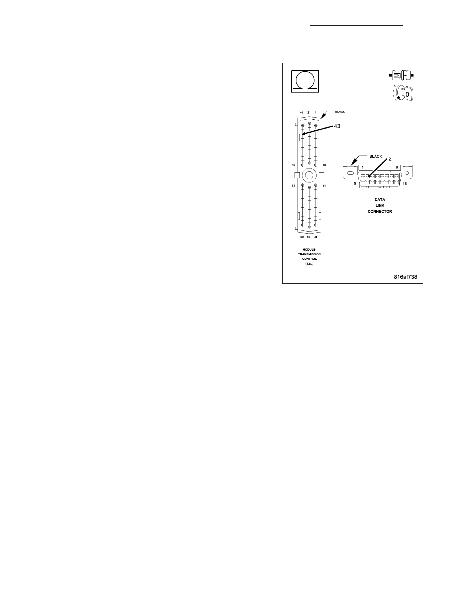
5.
(D25) PCI BUS CIRCUIT OPEN
Turn the ignition off.
Disconnect the scan tool from the DLC connector.
Measure the resistance of the (D25) PCI Bus circuit between the DLC
and the TCM connector.
Is the resistance below 5.0 ohms?
Yes
>> Replace the Transmission Control Module in accordance
with the service information.
Perform the appropriate POWERTRAIN VERIFICATION
TEST.
No
>> Repair the (D25) PCI Bus circuit for an open.
Perform the appropriate POWERTRAIN VERIFICATION
TEST.
8E - 120
ELECTRONIC CONTROL MODULES - ELECTRICAL DIAGNOSTIC
KJ