Jeep Liberty KJ. Manual - part 1462


  Index      Jeep     Jeep Liberty KJ - service repair manual 2006 year


Search            


Content   ..  1460  1461  1462  1463   ..


Jeep Liberty KJ. Manual - part 1462


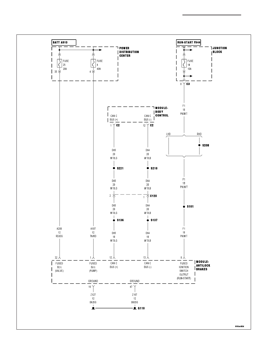
*NO RESPONSE FROM ABS (ANTILOCK BRAKE MODULE)

For a complete wiring diagram Refer to Section 8W.

8E - 60

ELECTRONIC CONTROL MODULES - ELECTRICAL DIAGNOSTIC

KJ

Possible Causes

(A107) (A200) FUSED B(+) CIRCUIT OPEN OR SHORTED

(Z107) (Z127) GROUND CIRCUIT OPEN

(F1) FUSED IGNITION SWITCH OUTPUT CIRCUIT OPEN OR SHORTED

(D65) CAN C BUS (+) CIRCUIT OPEN

(D64) CAN C BUS (-) CIRCUIT OPEN

ANTILOCK BRAKE MODULE

Diagnostic Test

1.

TEST FOR INTERMITTENT CONDITION

Turn the ignition on.

NOTE: Ensure the IOD fuse is installed and battery voltage is between 10.0 and 16.0 volts.
With the scan tool, select ECU view.

NOTE: A red X will be next to the module that is not communicating, indicating that the module is not active
on the Bus network. A green check indicates that the module is active on the Bus network.

Does the scan tool display a red X next to the module?

Yes

>> Go To 2

No

>> The no response condition is not present at this time. Using the wiring diagram/schematic as a guide,

inspect the wiring for chafed, pierced, pinched, and partially broken wires and the wiring harness con-
nectors for broken, bent, pushed out, and corroded terminals.

2.

(A107) (A200) FUSED B(+) CIRCUIT OPEN OR SHORTED

Turn the ignition off.

Disconnect the Antilock Brake Module harness connector.

Using a 12-volt test light connected to ground, check each (A107) and
(A200) Fused B(+) circuit.

Does the test light illuminate brightly for each circuit?

Yes

>> Go To 3

No

>> Repair the (A107) or (A200) Fused B(+) circuit for an open

or short.

Perform ABS VERIFICATION TEST - VER 1.

KJ

ELECTRONIC CONTROL MODULES - ELECTRICAL DIAGNOSTIC

8E - 61

3.

(Z107) (Z127) GROUND CIRCUIT OPEN

Using a 12-volt test light connected to 12-volts, check each (Z107) and
(Z127) ground circuit.

Does the test light illuminate brightly for each circuit?

Yes

>> Go To 4

No

>> Repair the (Z107) or (Z127) ground circuit for an open.

Perform ABS VERIFICATION TEST - VER 1.

4.

(F1) FUSED IGNITION SWITCH OUTPUT CIRCUIT OPEN OR SHORTED

Turn the ignition on.

Using a 12-volt test light connected to ground, check the (F1) Fused
Ignition Switch Output circuit.

Does the test light illuminate brightly?

Yes

>> Go To 5

No

>> Repair the (F1) Fused Ignition Switch Output circuit for an

open or short.

Perform ABS VERIFICATION TEST - VER 1.

8E - 62

ELECTRONIC CONTROL MODULES - ELECTRICAL DIAGNOSTIC

KJ

5.

(D65) CAN C BUS (+) CIRCUIT OPEN

Turn the ignition off.

Disconnect the scan tool from the DLC connector.

Measure the resistance of the (D65) CAN C Bus (+) circuit between the
DLC connector and the Antilock Brake Module connector.

Is resistance below 5.0 ohms?

Yes

>> Go To 6

No

>> Repair the (D65) CAN C Bus (+) circuit for an open.

Perform ABS VERIFICATION TEST - VER 1.

6.

(D64) CAN C BUS (-) CIRCUIT OPEN

Measure the resistance of the (D64) CAN C Bus (-) circuit between the
DLC connector and the Antilock Brake Module connector.

Is resistance below 5.0 ohms?

Yes

>> Replace the Antilock Brake Module in accordance with the

service information.

Perform ABS VERIFICATION TEST - VER 1.

No

>> Repair the (D64) CAN C Bus (-) circuit for an open.

Perform ABS VERIFICATION TEST - VER 1.

KJ

ELECTRONIC CONTROL MODULES - ELECTRICAL DIAGNOSTIC

8E - 63


Content   ..  1460  1461  1462  1463   ..