Content .. 1451 1452 1453 1454 ..
Jeep Liberty KJ. Manual - part 1453
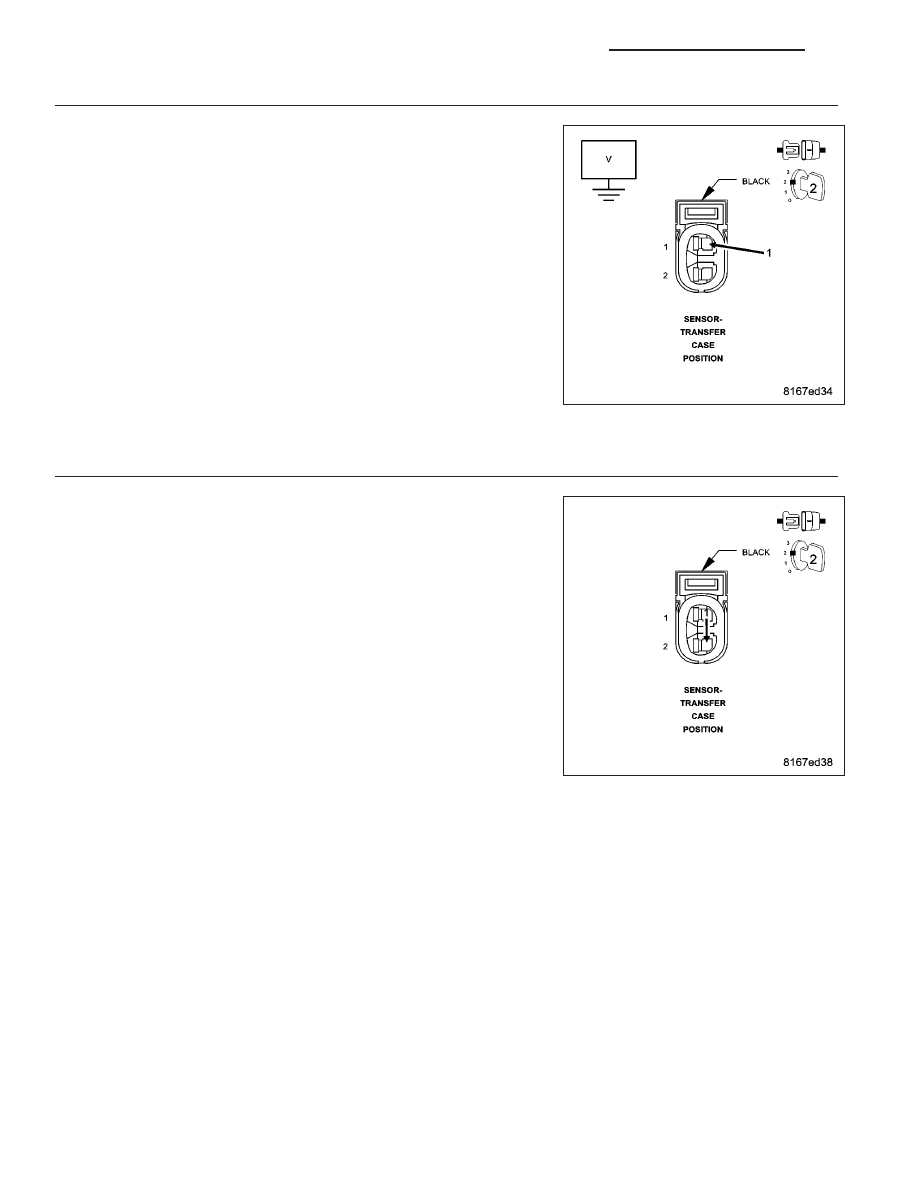
3.
CHECK THE (K77) TRANSFER CASE POSITION SENSOR INPUT CIRCUIT FOR A SHORT TO VOLTAGE
Turn the ignition off.
Disconnect the BCM C2 harness connector.
Turn the ignition on.
Measure the voltage of the (K77) Transfer Case Position Sensor Input
circuit at the Transfer Position Sensor harness connector.
Is the voltage above 0.2 volts?
Yes
>> Repair the (K77) Transfer Case Position Sensor Input circuit
for a short to voltage.
No
>> Replace and program the BCM in accordance with the Ser-
vice Information.
Perform BODY VERIFICATION TEST - VER 1. (Refer to 8 -
ELECTRICAL/ELECTRONIC
CONTROL
MODULES
-
STANDARD PROCEDURE).
4.
CHECK THE (K77) TRANSFER CASE POSITION SENSOR INPUT CIRCUIT & THE (K300) SENSOR
GROUND CIRCUIT FUNCTION
Turn the ignition off.
Connect a jumper wire between the (K77) Transfer Case Position Sen-
sor Input circuit and the (K300) Sensor Ground circuit.
Turn the ignition on.
With the scan tool, read the Transfer Case Position Sensor Input volt-
age.
Is the voltage below 1.0 volt?
Yes
>> Replace the Transfer Case Position Sensor in accordance
with the Service Information.
Perform BODY VERIFICATION TEST - VER 1. (Refer to 8 -
ELECTRICAL/ELECTRONIC
CONTROL
MODULES
-
STANDARD PROCEDURE).
No
>> Go To 5
8E - 24
ELECTRONIC CONTROL MODULES - ELECTRICAL DIAGNOSTIC
KJ