Jeep Liberty KJ. Manual - part 1402


  Index      Jeep     Jeep Liberty KJ - service repair manual 2006 year


Search            


Content   ..  1400  1401  1402  1403   ..


Jeep Liberty KJ. Manual - part 1402


SPECIAL TOOLS

HEATING-A/C SYSTEM

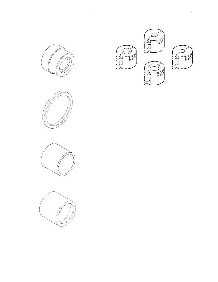
Compressor Field Coil Installer 9352

Compressor Field Coil Installer Spacer 9353

Compressor Field Coil Remover 9354

Clutch Pulley Installer 9355

A/C Line Disconnect Tools 7193

24 - 10

HEATING & AIR CONDITIONING

KJ

CONTROLS

TABLE OF CONTENTS

page

page

ACTUATOR-BLEND DOOR

DESCRIPTION . . . . . . . . . . . . . . . . . . . . . . . . . . . . . . . . 12
OPERATION . . . . . . . . . . . . . . . . . . . . . . . . . . . . . . . . . . 12
REMOVAL . . . . . . . . . . . . . . . . . . . . . . . . . . . . . . . . . . . . 12
INSTALLATION . . . . . . . . . . . . . . . . . . . . . . . . . . . . . . . 13

ACTUATOR-MODE DOOR

DESCRIPTION . . . . . . . . . . . . . . . . . . . . . . . . . . . . . . . . 14
REMOVAL . . . . . . . . . . . . . . . . . . . . . . . . . . . . . . . . . . . . 14
INSTALLATION . . . . . . . . . . . . . . . . . . . . . . . . . . . . . . . 15

ACTUATOR-RECIRCULATION DOOR

DESCRIPTION . . . . . . . . . . . . . . . . . . . . . . . . . . . . . . . . 16
REMOVAL . . . . . . . . . . . . . . . . . . . . . . . . . . . . . . . . . . . . 16
INSTALLATION . . . . . . . . . . . . . . . . . . . . . . . . . . . . . . . 17

CLUTCH-A/C COMPRESSOR

DESCRIPTION . . . . . . . . . . . . . . . . . . . . . . . . . . . . . . . . 18
OPERATION . . . . . . . . . . . . . . . . . . . . . . . . . . . . . . . . . . 18
DIAGNOSIS AND TESTING

A/C COMPRESSOR CLUTCH COIL . . . . . . . . . . . 18

STANDARD PROCEDURE

A/C CLUTCH PLATE INSPECTION . . . . . . . . . . . 19
A/C CLUTCH BREAK-IN . . . . . . . . . . . . . . . . . . . . . 20

REMOVAL

DENSO A/C COMPRESSOR . . . . . . . . . . . . . . . . . 20
VISTEON A/C COMPRESSOR . . . . . . . . . . . . . . . . 22

INSTALLATION

DENSO A/C COMPRESSOR . . . . . . . . . . . . . . . . . 25
VISTEON A/C COMPRESSOR . . . . . . . . . . . . . . . . 27

CONTROL-A/C HEATER

DESCRIPTION . . . . . . . . . . . . . . . . . . . . . . . . . . . . . . . . 30
DIAGNOSIS AND TESTING

VACUUM CONTROL SYSTEM . . . . . . . . . . . . . . . . 30

REMOVAL . . . . . . . . . . . . . . . . . . . . . . . . . . . . . . . . . . . . 33
INSTALLATION . . . . . . . . . . . . . . . . . . . . . . . . . . . . . . . 33

RELAY-A/C CLUTCH

DESCRIPTION . . . . . . . . . . . . . . . . . . . . . . . . . . . . . . . . 34
OPERATION . . . . . . . . . . . . . . . . . . . . . . . . . . . . . . . . . . 34
REMOVAL . . . . . . . . . . . . . . . . . . . . . . . . . . . . . . . . . . . . 35
INSTALLATION . . . . . . . . . . . . . . . . . . . . . . . . . . . . . . . 35

RELAY-BLOWER MOTOR

DESCRIPTION . . . . . . . . . . . . . . . . . . . . . . . . . . . . . . . . 36
OPERATION . . . . . . . . . . . . . . . . . . . . . . . . . . . . . . . . . . 36
REMOVAL . . . . . . . . . . . . . . . . . . . . . . . . . . . . . . . . . . . . 37
INSTALLATION . . . . . . . . . . . . . . . . . . . . . . . . . . . . . . . 37

RESISTOR-BLOWER MOTOR

DESCRIPTION . . . . . . . . . . . . . . . . . . . . . . . . . . . . . . . . 38
OPERATION . . . . . . . . . . . . . . . . . . . . . . . . . . . . . . . . . . 38
DIAGNOSIS AND TESTING

BLOWER MOTOR RESISTOR . . . . . . . . . . . . . . . . 38

REMOVAL . . . . . . . . . . . . . . . . . . . . . . . . . . . . . . . . . . . . 39
INSTALLATION . . . . . . . . . . . . . . . . . . . . . . . . . . . . . . . 40

SWITCH-A/C HIGH PRESSURE

DESCRIPTION . . . . . . . . . . . . . . . . . . . . . . . . . . . . . . . . 41
OPERATION . . . . . . . . . . . . . . . . . . . . . . . . . . . . . . . . . . 41
DIAGNOSIS AND TESTING

A/C HIGH PRESSURE SWITCH . . . . . . . . . . . . . . 41

REMOVAL . . . . . . . . . . . . . . . . . . . . . . . . . . . . . . . . . . . . 42
INSTALLATION . . . . . . . . . . . . . . . . . . . . . . . . . . . . . . . 42

SWITCH-A/C-LOW PRESSURE

DESCRIPTION . . . . . . . . . . . . . . . . . . . . . . . . . . . . . . . . 43
OPERATION . . . . . . . . . . . . . . . . . . . . . . . . . . . . . . . . . . 43
DIAGNOSIS AND TESTING

A/C LOW PRESSURE SWITCH . . . . . . . . . . . . . . . 43

REMOVAL . . . . . . . . . . . . . . . . . . . . . . . . . . . . . . . . . . . . 44
INSTALLATION . . . . . . . . . . . . . . . . . . . . . . . . . . . . . . . 44

TRANSDUCER-A/C PRESSURE

DESCRIPTION . . . . . . . . . . . . . . . . . . . . . . . . . . . . . . . . 45
OPERATION . . . . . . . . . . . . . . . . . . . . . . . . . . . . . . . . . . 45
DIAGNOSIS AND TESTING

A/C PRESSURE TRANSDUCER . . . . . . . . . . . . . . 45

REMOVAL . . . . . . . . . . . . . . . . . . . . . . . . . . . . . . . . . . . . 46
INSTALLATION . . . . . . . . . . . . . . . . . . . . . . . . . . . . . . . 46

VALVE-VACUUM CHECK

DESCRIPTION . . . . . . . . . . . . . . . . . . . . . . . . . . . . . . . . 48
OPERATION . . . . . . . . . . . . . . . . . . . . . . . . . . . . . . . . . . 48
REMOVAL . . . . . . . . . . . . . . . . . . . . . . . . . . . . . . . . . . . . 48
INSTALLATION . . . . . . . . . . . . . . . . . . . . . . . . . . . . . . . 49

KJ

CONTROLS

24 - 11

ACTUATOR-BLEND DOOR

DESCRIPTION

The heating-A/C system uses a reversible, 12-volt
direct current (DC) servo motor which mechanically
positions the blend-air door. The blend door actuator
(1) is located on the top of the HVAC housing.

The blend door actuator is contained within a black
molded plastic housing with an integral wire connector
receptacle (2) and three integral mounting tabs (3)
that allow the actuator to be secured to the HVAC
housing. The blend door actuator also has an output
shaft with splines that connects it to the linkage that
drives the blend-air door. The blend door actuator
requires mechanical indexing to the blend door
linkage.

OPERATION

The blend door actuator is connected to the A/C-heater control through the vehicle electrical system by a dedicated
three-wire lead and connector of the instrument panel wire harness. The blend door actuator can move the blend-air
door in two directions. A potentiometer within the actuator allows the A/C-heater control to know the exact position
of the blend-air door at all times.

The blend door actuator can be diagnosed using a scan tool. Refer to 9 - Engine Electrical Diagnostics for more
information.

The blend door actuator cannot be adjusted or repaired and, if faulty or damaged, it must be replaced.

REMOVAL

WARNING: On vehicles equipped with airbags, disable the airbag system before attempting any steering
wheel, steering column, or instrument panel component diagnosis or service. Disconnect and isolate the
negative battery (ground) cable, then wait two minutes for the airbag system capacitor to discharge before
performing further diagnosis or service. This is the only sure way to disable the airbag system. Failure to
take the proper precautions could result in accidental airbag deployment and possible personal injury or
death.

NOTE: Prior to performing this procedure, turn the ignition key to the On position and set the A/C-heater
control in the mid-temperature position and wait 10 seconds.

24 - 12

CONTROLS

KJ

NOTE: LHD model shown in illustration. RHD mod-
els similar.

1. Remove the instrument panel from the vehicle

(Refer to 23 - BODY/INSTRUMENT PANEL -
REMOVAL).

2. Remove the three screws (1) that secure the blend

door actuator (2) to the top of the HVAC housing
(3) near the heater core (4).

NOTE: Note the actuator shaft position for instal-
lation reference.

3. Remove the blend door actuator from the HVAC

housing and disconnect the wire harness connector
(5) from the actuator.

4. Remove the blend door actuator from the vehicle.

INSTALLATION

NOTE: LHD model shown in illustration. RHD mod-
els similar.

1. Position the blend door actuator (2) onto the top of

the HVAC housing (3) near the heater core (4),
making sure the actuator spline is positioned prop-
erly with the door spline. If necessary, rotate the
actuator slightly to align the splines on the actuator
output shaft with those on the blend door pivot.

2. Install the three screws (1) that secure the blend

door actuator to the HVAC housing. Tighten the
screws to 2 N·m (17 in. lbs.).

3. Connect the wire harness connector (5) to the

blend door actuator.

4. Install the instrument panel (Refer to 23 - BODY/

INSTRUMENT PANEL - INSTALLATION).

KJ

CONTROLS

24 - 13


Content   ..  1400  1401  1402  1403   ..