Jeep Liberty KJ. Manual - part 1318


  Index      Jeep     Jeep Liberty KJ - service repair manual 2006 year


Search            


Content   ..  1316  1317  1318  1319   ..


Jeep Liberty KJ. Manual - part 1318
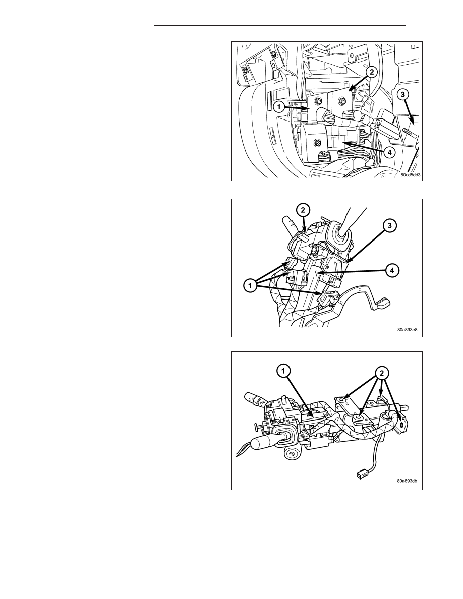


21. Connect the wiring harness electrical connectors

at the junction block.

22. Connect the wire harness electrical connector

behind the driver’s side cowl trim cover.

23. Install the driver’s side cowl trim cover. (Refer to

23 - BODY/INTERIOR/COWL TRIM COVER -
INSTALLATION)

CAUTION: Do not remove the brake lamp switch.
This is a one time component and is not intended
for reinstallation. If the brake lamp switch is
removed it must be discarded and replaced with a
new switch.

24. Connect

the

brake

lamp

switch

electrical

connector.

25. Install the steering column into the vehicle.

26. Slide the shifter interlock cable into the tie straps.

27. Install and connect the wire harness for the

column.

28. Install the two mounting nuts and the two mount-

ing bolts all finger tight.

CAUTION: Lower nuts must be installed and tight-
ened first then the upper nuts in order to prevent
damage to the capsules.

29. Tighten the lower mounting nuts to 17 N·m (13 ft.

lbs.).

30. Tighten the upper mounting nuts to 17 N·m (13 ft.

lbs.).

31. Install the steering column coupler bolt and

tighten to 49 N·m (36 ft. lbs.).

32. Install the upper and lower shrouds and install the

screws.

33. Install the knee blocker cover and knee blocker.

(Refer to 23 - BODY/INSTRUMENT PANEL/KNEE BLOCKER - INSTALLATION)

23 - 172

INSTRUMENT PANEL

KJ

34. Install the ground strap and bolt and connect the restraint module electrical connector.

35. Install the center support bracket (2) and hold it tight against the instrument panel.

36. Tighten the lower nuts to 23 N·m (17 ft. lbs.).

37. Tighten the upper bracket nuts to 23 N·m (17 ft. lbs.).

38. Install the radio. (Refer to 8 - ELECTRICAL/AU-

DIO/RADIO - INSTALLATION)

KJ

INSTRUMENT PANEL

23 - 173

39. Install the floor console. (Refer to 23 - BODY/IN-

TERIOR/FLOOR CONSOLE - INSTALLATION)

40. Install the speakers. (Refer to 8 - ELECTRICAL/

AUDIO/SPEAKER - INSTALLATION)

41. Reconnect the battery ground cable.

23 - 174

INSTRUMENT PANEL

KJ

INSTRUMENT PANEL TOP COVER

REMOVAL

1. Before proceeding with the following repair proce-

dure, review all warnings and cautions. (Refer to
23 - BODY/INSTRUMENT PANEL - WARNING)

2. Remove the A-pillar trim. (Refer to 23 - BODY/IN-

TERIOR/A-PILLAR TRIM AND GRAB HANDLE -
REMOVAL)

3. Using a trim stick C-4755 or equivalent, release the

attachment clips and remove the top cover (3).

INSTALLATION

1. Before proceeding with the following repair proce-

dure, review all warnings and cautions. (Refer to
23 - BODY/INSTRUMENT PANEL - WARNING)

2. Position the top cover (3) and seat the clips fully.

3. Install the A-pillar trim panels. (Refer to 23 - BODY/

INTERIOR/A-PILLAR TRIM AND GRAB HANDLE -
INSTALLATION)

KJ

INSTRUMENT PANEL

23 - 175


Content   ..  1316  1317  1318  1319   ..